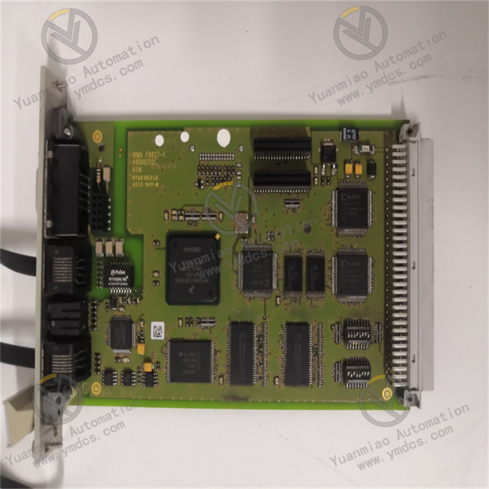
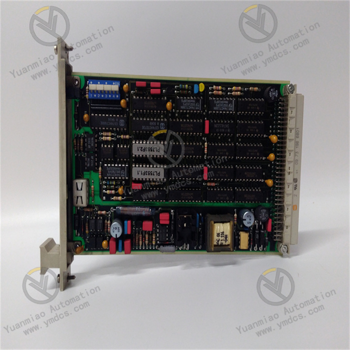
Description
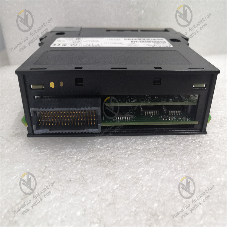
Hardware Overview Processor Performance: Equipped with a high-performance processor, it can quickly handle complex logical operations and data processing tasks. For the 1756-L55M13, it has specific processing capabilities and memory configurations, which can meet various industrial automation control requirements. It can usually support a large number of input/output points (I/O) and can handle multiple communication tasks, providing strong hardware support for the centralized control of industrial systems. Memory Configuration: It has a certain capacity of user program memory and data memory. The user program memory is used to store the written control logic program, and the data memory is used to store various data during operation, such as input/output status, intermediate variables, operation results, etc. Sufficient memory space allows for the storage of large-scale programs and a large amount of data to adapt to complex industrial control scenarios. Communication Capability: It has a variety of communication interfaces and supports multiple communication protocols, such as EtherNet/IP, ControlNet, DeviceNet, etc. Through these communication interfaces and protocols, it can conveniently communicate with other devices, such as the host computer monitoring system, other PLCs, intelligent instruments, frequency converters, etc., to exchange data and work collaboratively, realizing the integrated and networked control of industrial systems.
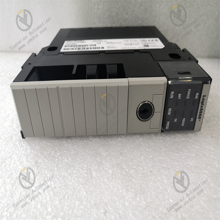
Working Principle
Scanning Cycle: It adopts a cyclic scanning working mode, continuously performing three stages of input sampling, program execution, and output refreshing. During the input sampling stage, the PLC reads the external signal status on the input module and stores it in the input image register; during the program execution stage, according to the user-written control program, it reads data from the input image register and other internal registers for logical operation and processing; during the output refreshing stage, it outputs the program execution result from the output image register to the output module to control the operation of external devices. This cyclic scanning mode enables the PLC to respond in real-time to changes in external signals and perform precise control according to the predetermined control logic.
Programming Method: It uses Rockwell Automation's Logix platform programming software, such as RSLogix 5000 for programming. It supports multiple programming languages, including Ladder Diagram, Structured Text, Function Block Diagram, etc. Users can select appropriate programming languages according to their habits and the complexity of the control tasks. Through the programming software, users can conveniently write, debug, download, and monitor programs, achieving flexible control of industrial processes.
Functional Features
High Reliability: It adopts a variety of reliability design measures, such as redundant power supplies, hot-swappable functions, a sturdy housing design, anti-interference circuits, etc. The redundant power supply ensures that the system can still operate normally when one power supply fails; the hot-swappable function allows modules to be replaced without interrupting the system operation, facilitating maintenance and upgrades; the sturdy housing and anti-interference circuits can adapt to harsh industrial environments, ensuring that the PLC can operate stably under conditions such as strong electromagnetic interference, high temperature, and humidity.
Strong Flexibility: The ControlLogix series PLC has a modular structure, and the 1756-L55M13 can be combined with various types of I/O modules, communication modules, functional modules, etc. The system can be flexibly configured according to different control requirements. Users can select appropriate modules for expansion according to the scale and complexity of the actual project, achieving integrated control from small-scale single-machine control to large and complex industrial systems.
Powerful Instruction Set: It provides a rich instruction set, including logical operation instructions, data processing instructions, timer/counter instructions, communication instructions, etc. These instructions can meet the needs of various industrial control tasks, such as logical control, sequential control, process control, motion control, etc. By flexibly using these instructions, users can write efficient and precise control programs to achieve complex control of industrial equipment and production processes.
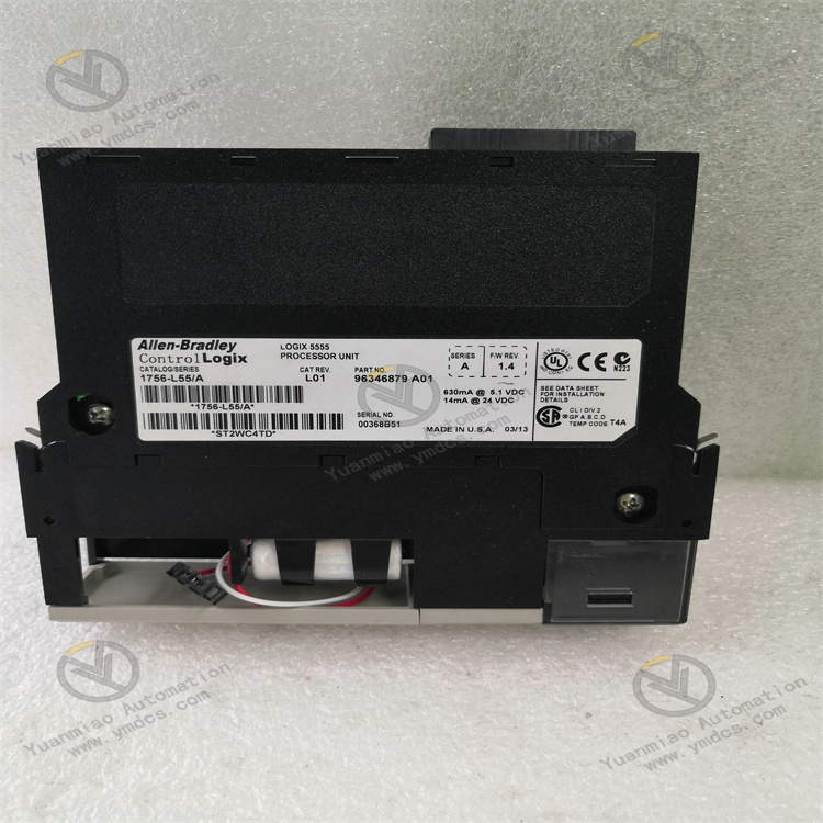
Technical Parameters Power Supply Specifications: It usually supports multiple power supply voltage inputs, commonly including 120/240V AC or 24V DC power supplies. It has good power supply adaptability and can operate stably within a certain voltage fluctuation range, providing a reliable power supply for the PLC and the devices connected to it. I/O Point Support: Different numbers of I/O modules can be connected according to the actual configuration, thus supporting different scales of I/O points. Generally, the ControlLogix system can support a large number of I/O points, and the 1756-L55M13 can meet the I/O requirements of most medium to large-scale industrial automation projects. It can be connected to digital input/output modules, analog input/output modules, special function modules, etc., to collect and control various types of signals. Communication Rate: Different communication interfaces have different communication rates. For example, the EtherNet/IP interface usually supports a communication rate of 100Mbps, which can quickly transmit a large amount of data to meet the application scenarios with high real-time requirements in industrial control; the communication rate of the ControlNet interface can also meet the real-time control requirements of the industrial field, ensuring efficient data interaction between the PLC and other devices. Application Scenarios Automobile Manufacturing Production Line: It is used for various automation control tasks in the automobile production process, such as body welding, assembly line control, robot control, etc. By communicating with various sensors, actuators, and robots, it can achieve precise control and coordination of the production process, improve production efficiency and product quality, and ensure the efficient and stable operation of automobile production. Chemical Production Process Control: In chemical production, precise control of various process parameters such as temperature, pressure, flow rate, and liquid level is crucial. The 1756-L55M13 can be connected to various analog and digital sensors to collect process parameter data in real-time, and perform calculations and processing according to the preset control strategy. By controlling devices such as valves, pumps, and compressors, it can achieve automated control of the chemical production process, ensuring the safety, stability, and efficiency of the production process, and improving product quality and production benefits. Power System Monitoring and Control: In power systems such as power plants and substations, it is used to monitor and control the operation status of power equipment. It can be connected to various power sensors, protection devices, and switchgear to collect parameters such as voltage, current, and power of the power system in real-time, and achieve fault diagnosis, protection control, and remote monitoring of the power system to ensure the safe and reliable operation of the power system.
Some Common Faults and Solutions:
1. Power Supply Fault
Fault Phenomenon: The PLC cannot start normally, and the power indicator light does not turn on.
Cause Analysis: It may be due to a damaged power supply module, an input power supply fault, or poor power supply wiring.
Solution: Check if there are signs of damage to the power supply module, such as bulging capacitors, abnormal odors, etc., and replace the power supply module if necessary. Measure whether the input power supply voltage is within the specified range, and check if the power supply wiring is firm. Reconnect it if it is loose.
2. Communication Fault
Fault Phenomenon: It cannot establish communication with other devices (such as touch screens, frequency converters, etc.), or the communication data transmission is unstable and lost.
Cause Analysis: Incorrect communication parameter settings, damaged communication cables, communication interface faults, or network interference.
Solution: Confirm whether the communication parameter settings are correct, including baud rate, data bits, stop bits, parity, etc., and ensure they are consistent with the communication partner device. Check if the communication cable is damaged, broken, etc., and replace the cable if necessary. Check if the communication interface is loose or damaged, and try to reinsert or replace the communication module. Investigate whether there are strong electromagnetic interference sources around, and take shielding measures or adjust the device layout.
3. Abnormal Program Operation
Fault Phenomenon: The program running on the PLC has logical errors, freezes, or stops unexpectedly.
Cause Analysis: Programming errors, insufficient memory, module compatibility issues, or hardware faults.
Solution: Use the programming software to debug the program and check for and correct logical errors. Check the memory usage of the PLC, and optimize the program or add memory modules if necessary. Confirm whether the modules in use are compatible with the PLC model, and replace the appropriate modules if there is an incompatibility. Conduct hardware diagnosis on the PLC, check for faulty modules, and replace the faulty modules if any.
4. Input/Output Fault
Fault Phenomenon: There is no signal input at the input points, and the output points cannot drive the load normally.
Cause Analysis: Damaged input/output modules, poor wiring, load faults, or incorrect configuration of input/output in the PLC program.
Solution: Check the indicator lights on the input/output modules to determine if there is signal input or output. If the indicator lights do not turn on, check if the corresponding wiring is correct, and if there is looseness or open circuit. If the wiring is normal, try to replace the input/output modules. Check if the load device is working properly, such as whether the motor is burned out, whether the valve is stuck, etc. Check the configuration and logical control of the input/output points in the PLC program to ensure the program is correct.
5. Overheating Fault
Fault Phenomenon: The temperature of the PLC housing is too high, and it may stop due to overheating protection.
Cause Analysis: Poor heat dissipation, too high ambient temperature, or internal component short circuit causing abnormal heating.
Solution: Check whether the installation position of the PLC has good ventilation, and whether there are other heating devices around that affect heat dissipation. Clean the surface and heat dissipation holes of the PLC to ensure the heat dissipation channel is unobstructed. If the ambient temperature is too high, consider adding heat dissipation devices, such as air conditioners, fans, etc. Use professional tools to detect whether there are component short circuits or damage inside the PLC, and replace the damaged components if any.


