Description
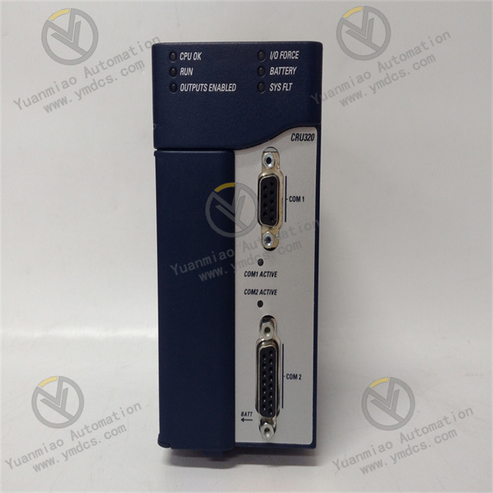
GE IC695CRU320
The GE IC695CRU320 is a 10-slot rack unit for the PACSystems RX3i series industrial automation control systems. Serving as the core carrier for module installation, signal transmission, and system power supply, it undertakes the functions of physical fixation and data interaction for key modules such as CPU, power supply, and I/O. Its core positioning is to provide a stable "hardware framework" for the RX3i system. Through standardized installation interfaces and a high-speed backplane bus, it enables the collaborative operation of various modules. Widely used in small and medium-sized industrial control scenarios such as intelligent manufacturing production lines, chemical DCS systems, and power equipment monitoring platforms, it is a fundamental component that ensures system integration efficiency and operational stability.
I. Technical Parameters
- Installation and Slot Parameters: Adopts a standard 10-slot design, compatible with all specifications of RX3i series modules; slot spacing is 20mm, supporting hot swapping of modules (requires the module itself to have hot-swappable functionality); maximum load capacity per slot is 500g, with a plug-in lifespan of ≥1000 times.
- Backplane Bus Parameters: Built-in high-speed parallel backplane bus with a data transmission rate of 1Gbps; bus delay ≤100ns, supporting real-time data synchronization among multiple modules; bus power supply capability: each slot provides DC 5V/2A power supply, with a total power supply capacity of DC 5V/20A.
- Physical and Structural Parameters: Dimensions are 483mm (width) × 178mm (height) × 140mm (depth), complying with the DIN EN 50022 standard; made of cold-rolled steel plate with surface plastic-sprayed treatment; protection class IP20, supporting DIN rail mounting or cabinet bolt fixing.
- Environmental Adaptability Parameters: Operating temperature ranges from 0℃ to 60℃, storage temperature ranges from -40℃ to 85℃; relative humidity is 5%-95% (non-condensing); vibration resistance level complies with IEC 60068-2-6 (10Hz~500Hz, acceleration 2g); shock resistance level complies with IEC 60068-2-27 (peak acceleration 10g, duration 11ms).
II. Functional Features
- Full-Series Module Compatibility for Flexible Configuration: The 10-slot design supports mixed installation of all RX3i series modules, including CPU modules (e.g., IC695CPE330), power supply modules (e.g., IC695PSA140), digital/analog I/O modules, and special function modules (e.g., high-speed counting, communication modules). No additional adapters are required, meeting system configuration needs for different scenarios.
- High-Speed Backplane Bus for Real-Time Collaboration: The 1Gbps high-speed bus ensures millisecond-level data interaction between the CPU and various I/O modules, with a bus delay ≤100ns. In scenarios involving linked control of multiple modules (such as coordinated start-stop of production line equipment), it enables precise synchronization of actions across modules, avoiding process deviations caused by signal transmission delays.
- Robust Structure and Anti-Looseness Design for Enhanced Anti-Interference Capability: The cold-rolled steel plate material and reinforced guide rail design give the rack an impact resistance of 10J, enabling it to withstand vibrations and collisions in industrial sites; the module locking buckle adopts a wedge-shaped structure with a plug-in force of 15N, which can effectively prevent modules from loosening due to vibration and maintain stable performance in high-frequency vibration scenarios such as automobile welding and metallurgy.
- Easy Integration and Maintenance for Reduced Usage Costs: The standardized guide rail installation design allows rack fixation and module installation to be completed within 10 minutes; each slot is equipped with an LED status indicator to intuitively display the power supply and communication status of the module; the backplane bus uses gold-plated contacts to reduce contact resistance and minimize the risk of faults caused by contact oxidation.
III. Working Principle
- Module Fixation and Positioning: Various functional modules (power supply, CPU, I/O) are accurately inserted through the guide rails of the rack slots. The locking buckles automatically engage to achieve mechanical fixation, ensuring tight contact between the modules and the backplane bus contacts, and providing a physical foundation for power supply and signal transmission.
- Power Distribution: After the power supply module is installed in the designated slot, DC power is distributed to each slot through the power supply lines of the backplane bus. The rack has a built-in overcurrent protection circuit, which automatically limits the current when the current of a single slot exceeds 2A to prevent module damage due to overload.
- Signal Transmission and Collaboration: The CPU module issues control commands to each I/O module via the backplane bus, and on-site signals collected by the I/O modules are fed back to the CPU through the bus; the high-speed bus adopts a parallel transmission architecture, which can transmit multiple sets of signals simultaneously, realizing real-time data interaction between the CPU and all modules and ensuring the collaborative operation of the system.
IV. Common Faults and Troubleshooting Methods
- Fault 1: A module in a certain slot fails to communicate, and the indicator light is offPossible causes: Poor contact of contacts due to loose module insertion, faulty power supply line in the slot, or faulty module itself.
- Troubleshooting: ① Power off, reinsert the module, and ensure the locking buckle is fully engaged; ② Move the module to another slot for testing—if communication is restored, the original slot is faulty, and contact after-sales service for maintenance; ③ If the fault persists after slot replacement, test the module's power supply voltage to confirm whether the module is damaged.
- Fault 2: Multiple modules experience communication abnormalities simultaneously, and the CPU reports a bus faultPossible causes: Contamination or oxidation of the backplane bus, unstable power supply from the power module, or poor grounding of the rack.
- Troubleshooting: ① Power off, wipe the backplane bus contacts with anhydrous alcohol to remove dust and oxide layers; ② Test the output voltage of the power module to ensure it is DC 5V±0.1V—replace the power module if the voltage is unstable; ③ Check the rack's grounding resistance to ensure it is ≤4Ω, and re-tighten the grounding terminal.
- Fault 3: Modules frequently loosen in a vibrating environment, causing faultsPossible causes: Aging and failure of locking buckles, improper module installation, or unstable rack fixation.
- Troubleshooting: ① Replace aging locking buckles to ensure good elasticity of the buckles; ② Reinstall the module and confirm it is fully engaged by listening for a "click" sound; ③ Check the rack's fixing bolts, use double nuts for locking to prevent loosening, and install shock-absorbing pads if necessary.
- Fault 4: Slot current overload causes the power module to trip for protectionPossible causes: Excessive power consumption of the module in a single slot, short circuit of the module, or short circuit of the power supply line.
- Troubleshooting: ① Calculate the module power consumption—ensure the power consumption of the module in a single slot does not exceed 10W (DC 5V/2A); if overloaded, replace with a low-power module or install modules in a distributed manner; ② Disconnect the module in the overloaded slot, test the module's resistance to confirm whether there is a short circuit; ③ Inspect the backplane power supply line and locate and repair the short-circuit point.