Description
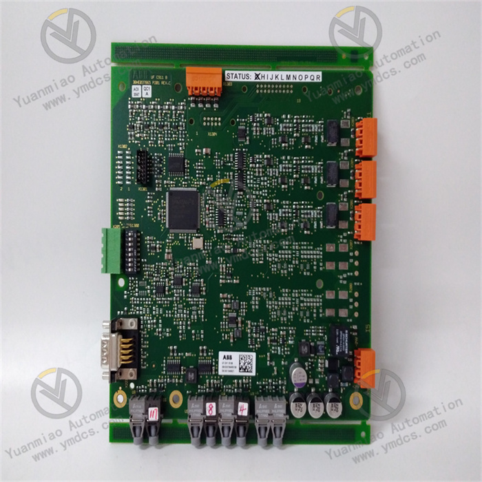
ABB AI835 3BSE008520R1
ABB AI835 3BSE008520R1 is an analog input module dedicated to receiving analog signals output by various industrial sensors such as those for temperature, pressure, flow rate, and liquid level. Through its internal precision signal conditioning, isolation, and A/D conversion circuits, it converts analog signals into digital signals recognizable by controllers, providing reliable data support for industrial scenarios including process control, data monitoring, and fault early warning. Equipped with multi-channel acquisition capability, flexible signal adaptation features, and basic diagnostic functions, it adopts an industrial-grade stable design and is widely used in fields with high requirements for signal acquisition stability, such as machinery manufacturing, power distribution, municipal engineering, and light industry. It can be seamlessly integrated with ABB series controllers and dedicated terminal units to ensure the efficient and stable operation of automated systems.
I. Product Features
1. Multi-channel Acquisition with Flexible Signal Adaptation
2. High-precision Conversion for Reliable Data Acquisition
3. Isolation Protection Design with Strong Anti-interference Capability
4. Basic Onboard Diagnostics for Efficient Operation and Maintenance
5. Modular Architecture with Good Compatibility and Scalability
6. Wide Operating Temperature Range with Strong Environmental Adaptability
II. Technical Specifications
1. Basic Parameters
- Model: ABB AI835 3BSE008520R1
- Product Type: Analog Input Module
- Product Series: ABB S800 I/O Series
- Brand: ABB
- Application Fields: Machinery Manufacturing, Power Distribution, Municipal Engineering, Light Industry, Automated Production Lines
- Compatible Systems: Industrial automation systems such as ABB 800xA Distributed Control System
- Compatible Terminal Units: S800 I/O series terminal units such as TU 810, TU 812, TU 814
- Mounting Method: DIN Rail Mounting (Compliant with EN 50022 Standard)
- Net Weight: Approximately 0.32kg
- Warranty Period: 12 Months
- RoHS Compliance: Conforms to EU Directive 2011/65/EU (RoHS 2.0)
- WEEE Category: Category 5 (Small Electronic Equipment)
2. Electrical Parameters
- Number of Input Channels: 8 Channels (Configurable for Single-ended/Differential Mode)
- Input Signal Types: Current signals (4-20mA, 0-20mA), Voltage signals (0-10V, 1-5V), Thermal resistors (Pt100, Pt1000, Cu50, Cu100)
- Resolution: 12-bit
- Measurement Accuracy: ±0.1% FS (Current/Voltage signals), ±0.2℃ (Temperature signals, Pt100, -100℃~+600℃)
- Isolation Class: Isolation between input and output, input and power supply, rated isolation voltage 50V AC (Continuous)
- Transmitter Power Supply: 24V DC, current limit ≤20mA per channel
- Communication Protocol: Compatible with industrial standard protocols such as Modbus
- Power Consumption: Typical value ≤4W (Full-load operating condition)
- Response Time: ≤20ms (Current/Voltage signals), ≤1s (Temperature signals, Pt100)
3. Mechanical & Environmental Parameters
- Dimensions (W×H×D): 45mm×119mm×100mm
- Operating Temperature: -25℃~+70℃
- Storage Temperature: -40℃~+85℃
- Relative Humidity: 5%~95%RH (Non-condensing)
- Electromagnetic Immunity: Compliant with EN 55011 Group 1 Class A, EN 61000-4-2 (ESD), EN 61000-4-4 (Electrical Fast Transient) standards
- Vibration Resistance: Compliant with IEC 60068-2-6 standard, 10-150Hz, acceleration 5g
- Shock Resistance: Compliant with IEC 60068-2-27 standard, acceleration 15g, duration 11ms
- Protection Class: IP20 (Front-end protection after DIN rail mounting)
III. Working Principle
The core working logic of the ABB AI835 3BSE008520R1 analog input module follows the sequence of "Signal Access - Power Supply Guarantee - Conditioning & Preprocessing - Conversion & Transmission - Status Monitoring - Diagnostic Feedback". The specific workflow is as follows:
- Signal Access and Power Supply Guarantee: Analog signals output by front-end industrial sensors (e.g., pressure sensors, thermal resistors, etc.) are connected to the module's 8 input channels via dedicated terminals, and the single-ended or differential wiring mode can be selected according to the signal type. The module provides stable 24V DC power for sensors requiring power supply (e.g., 4-20mA two-wire sensors) through its built-in current-limited power supply circuit, while limiting the output current to avoid module damage caused by sensor short circuit or overload.
- Signal Conditioning and Preprocessing: The accessed analog signals first pass through the module's internal dedicated conditioning circuits and are processed specifically for different signal types—current signals are converted into voltage signals via precision resistors; thermal resistance temperature signals undergo signal amplification and linearization processing. At the same time, electromagnetic interference from industrial sites (e.g., interference generated by frequency converters and relays) is removed through filter circuits. Electrical isolation between input signals and backend circuits is then achieved through isolation circuits, further improving signal stability and system safety.
- A/D Conversion and Data Transmission: The preprocessed standard analog signals are sent to the 12-bit high-precision A/D conversion circuit and converted into digital signals. After being processed by the module's internal logic circuit, the digital signals are transmitted to controllers such as ABB 800xA via the S800 I/O system bus, providing data support for the decision-making and control of the control system.
- Status Monitoring and Diagnostic Feedback: The module real-time monitors its own power supply voltage, A/D conversion circuit working status, and input signal integrity of each channel (e.g., overrange, open circuit). When an abnormality is detected, it immediately activates the onboard diagnostic mechanism, generates fault information including fault location and type, feeds it back to the control system via the communication link, and triggers corresponding local alarm indicators (power alarm, channel alarm) to remind maintenance personnel to handle the problem in a timely manner.
IV. Common Troubleshooting
| Fault Phenomenon | Possible Causes | Troubleshooting and Solutions |
|---|---|---|
| Power indicator not lit, module unresponsive | Abnormal power supply (power failure, voltage out of range), loose or reversed polarity of power terminal wiring, poor connection between module and terminal unit, internal power circuit failure of the module | Use a multimeter to measure the voltage at the module's power terminals to ensure it meets the 24V DC±10% requirement; check if the power terminal wiring is firm and verify the correctness of polarity connection; inspect the connection between the module and the terminal unit to ensure it is properly seated and firm, re-plug to confirm reliable connection; if the above checks are all normal but the module remains unresponsive, internal power circuit failure may be the cause—contact ABB authorized after-sales service for repair or replacement. |
| Large deviation in collected data, unstable signals | Loose or poor connection of input signal cables, incorrect wiring mode (confusion between single-ended and differential mode), poor or ungrounded shielded cables, external electromagnetic interference, uncalibrated module or lost calibration parameters, sensor malfunction, ambient temperature beyond the module's adaptive range | Re-tighten the input signal terminal wiring and verify that the wiring mode matches the signal type (correct selection of single-ended/differential mode); check whether shielded cables are used for signal cables and ensure the shielding layer is grounded at one end (grounding at the controller end is recommended), keep away from strong interference sources such as frequency converters and high-voltage cables; calibrate the module's precision with a standard signal source and restore calibration parameters; connect the sensor to other normal channels for testing to determine if it is faulty, replace it if necessary; check the module's operating ambient temperature and take cooling or heat preservation measures if it exceeds the -25℃~+70℃ range. |
| No data collected from specific channels, channel alarm indicator lit | Loose or broken wiring of the channel, sensor malfunction or no power supply, incorrect wiring mode configuration, internal damage to the module channel | Re-tighten the signal wiring of the channel and check for cable breaks; inspect whether the corresponding sensor of the channel is powered normally, connect the sensor to other normal channels for testing to determine if it is faulty, repair or replace it if necessary; verify that the wiring mode configuration of the channel is correct and matches the signal type; if the above checks are all normal, internal damage to the module channel may be the cause—contact ABB authorized after-sales service for repair. |
| Abnormal temperature signal collection (e.g., large display deviation, no display) | Incorrect thermal resistor wiring (e.g., three-wire system connected as two-wire system), thermal resistor damage, module temperature signal conditioning circuit failure, loss of calibration parameters | Verify that the thermal resistor wiring method is correct (three-wire/four-wire system), ensure cable resistance matching, re-wire and fasten the connection; connect the thermal resistor to other normal channels for testing to determine if it is damaged, replace it if necessary; calibrate the module's temperature acquisition function with a standard temperature source and restore calibration parameters; if both the sensor and wiring are normal, module temperature signal conditioning circuit failure may be the cause—contact after-sales service for repair. |
| Module frequently triggers overall alarm, multi-channel data abnormal | Excessive fluctuation of module power supply voltage, poor connection between module and terminal unit, strong external electromagnetic interference, overall loss of module calibration parameters | Measure the module's power supply voltage, install a voltage stabilizer at the front end if the fluctuation is excessive; check the connection between the module and the terminal unit, re-plug and fasten it; strengthen electromagnetic interference protection, check the grounding of shielded cables and cable layout, keep away from strong interference sources; perform overall precision calibration on the module and restore calibration parameters; if the alarm is still frequent after calibration, contact after-sales service for further troubleshooting of module faults. |