Description
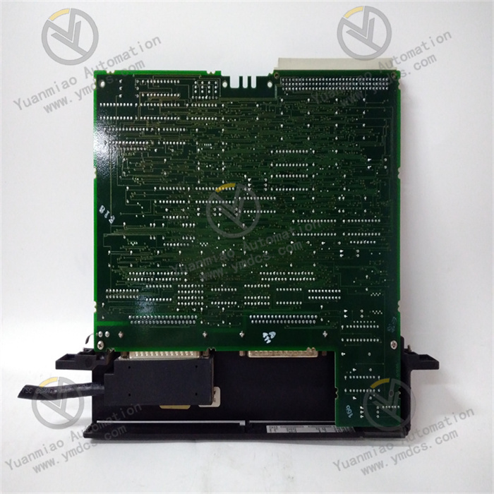
GE IC697BEM721
The GE IC697BEM721 is a processor module for the VersaMax series of Programmable Logic Controllers (PLCs). As the "computational and control core" of the PLC system, it mainly undertakes key tasks such as user program execution, I/O module management, data processing, communication coordination, and system diagnosis.
Its core function is to run control programs written in IEC 61131-3 standard programming languages (such as ladder logic and structured text) to collect real-time on-site signals (e.g., sensor data, switch status) from various I/O modules. After logical and arithmetic operations, it outputs control commands to drive the actions of actuators (e.g., valves, motors). Meanwhile, it has capabilities including multi-protocol communication, program storage and backup, and online debugging, making it suitable for the complex needs of small and medium-sized industrial automation control systems.
With balanced computing performance, flexible expandability, reliable industrial-grade design, and high cost-effectiveness, this module is widely used in production line control, equipment linkage, and process monitoring scenarios in fields such as food and beverage packaging, building materials production, warehousing and logistics, and small chemical equipment. It is a core component for building small and medium-sized high-reliability automation systems.
1. Technical Parameters
1.1 Computing Performance Parameters
1.2 Storage Capacity Parameters
1.3 Expansion and I/O Management Parameters
1.4 Communication and Environmental Parameters
2. Functional Features
2.1 Balanced Computing Efficiency for Small and Medium-Sized Control
The 400MHz high-frequency processor, combined with an optimized instruction set, ensures the fast execution of complex control programs for small and medium-sized systems. Even in scenarios with thousands of I/O points connected and multi-loop PID control running, it can still maintain a stable scan cycle. It supports complex operations such as floating-point arithmetic and trigonometric functions with an accuracy of ±1×10⁻⁶, meeting the high-precision requirements of scenarios such as temperature regulation in building materials production and quantitative control in food packaging. The multi-task scheduling function can assign control logic, data processing, and communication interaction to tasks of different priorities, preventing non-real-time tasks from affecting the control response speed.
2.2 Flexible Expansion Architecture to Reduce System Costs
It adopts a distributed architecture of "main rack + expansion racks". High-speed data interaction (with a transmission rate of 500Mbps) is achieved through the inter-rack bus. According to the on-site distribution of equipment, I/O modules can be installed in nearby expansion racks to reduce the length of signal cables and interference. It is compatible with all types of I/O modules in the VersaMax series (digital, analog, high-speed counters, pulse output modules, etc.). It can adapt to the collection and control needs of different signal types without replacing the processor, greatly improving system expandability, reducing later upgrade costs, and meeting the phased construction needs of small and medium-sized enterprises.
2.3 Dual Redundancy Design to Ensure Reliable Operation
It supports two core redundancy modes: Ethernet communication redundancy and power supply redundancy. The Ethernet ports support simple redundant configuration; in case of a communication link failure, manual switching to the standby link (or automatic switching via software) is available. When used with VersaMax series redundant power modules, it can realize uninterrupted switching of the power supply system, meeting the "low downtime" requirements of small and medium-sized production lines, with the overall system availability reaching over 99.99%. The module uses industrial-grade components and has passed strict high-low temperature, vibration, and shock tests, making it suitable for complex operating environments in workshops.
2.4 Multi-Protocol Communication and Convenient O&M
3. Working Principle
3.1 System Initialization and Configuration Loading
After the module is installed in the main rack, it automatically completes hardware self-test when powered on, including the status detection of the processor, memory, communication ports, and rack bus. Upon passing the self-test, it loads the user program and system configuration parameters (e.g., I/O module model, communication protocol, task priority) from the Flash memory. At the same time, it automatically identifies all I/O modules in the main rack and expansion racks, assigns module addresses, and establishes an I/O image area. After completing initialization, it enters the running state.
3.2 User Program Execution and Task Scheduling
The core processor schedules and executes user programs according to task priorities. High-priority tasks (e.g., real-time control logic, emergency shutdown logic) are executed first, while low-priority tasks (e.g., data log recording, report generation) are executed when high-priority tasks are idle. During program execution, it reads real-time collected on-site data from the I/O image area and performs logical operations such as ladder logic and structured text—for example, calculating valve adjustment quantities via the PID algorithm and determining equipment start-stop conditions through interlock logic. The operation results are stored in the output image area.
3.3 I/O Data Interaction and Control Output
The I/O scanner reads input signals (e.g., sensor digital quantities, analog values) from each I/O module at a set cycle (configurable from 1ms to 100ms), updates them to the input image area for program execution and calling. At the same time, it distributes the operation results in the output image area to the corresponding output modules to drive the actions of actuators (e.g., motor starters, solenoid valves), realizing precise control of the production process. It supports interrupt-triggered I/O interaction: when a key input such as an emergency stop signal is detected, it immediately triggers a high-priority interrupt service routine to quickly respond to control needs.
3.4 Communication Interaction and Status Monitoring
4. Common Faults and Solutions
4.1 Fault 1: Processor Fails to Start, Power Indicator Is Off or Flashing
Possible Causes
Solutions
4.2 Fault 2: No Data Collection or Abnormal Output in Some I/O Channels
Possible Causes
Solutions
4.3 Fault 3: Communication Interrupted with HMI or SCADA System
Possible Causes
Solutions
4.4 Fault 4: Abnormal Program Execution with Control Logic Errors
Possible Causes
Solutions