Description
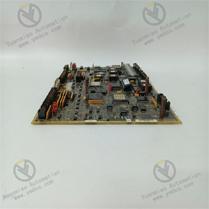
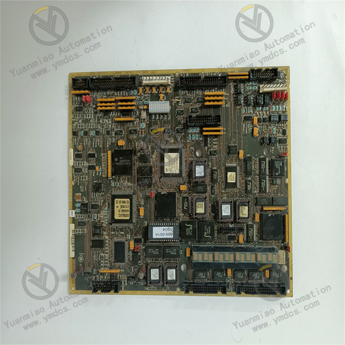
GE DS200LDCCH1AGA
I. Overview
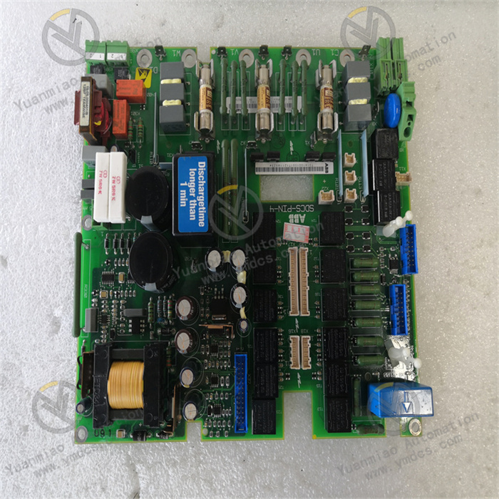
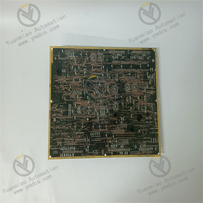
The GE DS200LDCCH1AGA is an excellent drive control board meticulously designed for complex industrial automation scenarios, playing a key role in the field of industrial control. It is mainly used for precise control of motor and other equipment operations, widely adapted to various industrial processes to ensure equipment operates with precision and efficiency.
This board belongs to GE's classic Mark V series, which is highly recognized in the industry for its outstanding high performance and reliability, demonstrating excellent performance in harsh industrial environments. Inheriting the fine genes of the Mark V series, the DS200LDCCH1AGA is perfectly compatible with GE's DIRECTO-MATIC 2000 drivers and exciters, providing solid equipment control support for numerous fields such as power systems and manufacturing.
Its multi-channel control design is a notable highlight, enabling real-time monitoring and precise control of multiple motors or equipment simultaneously, greatly enhancing the overall operational efficiency and coordination of industrial automation systems. For example, on the automated production lines of large factories, where multiple motors work collaboratively, the DS200LDCCH1AGA can synchronously monitor the operating status of these motors to ensure smooth and stable production processes.
In terms of communication, the board supports multiple communication interfaces, including common methods such as Ethernet, serial ports (RS-232, RS-485), and Modbus. This allows it to conveniently interact data with other devices and control systems, easily integrate into various complex industrial automation networks, achieve efficient data transmission and sharing, and lay a foundation for the intelligent and integrated development of industrial systems.
User programmability is also a significant advantage. Users can flexibly configure and program it using programming software according to actual industrial production needs, making the board's functions precisely fit the special requirements of different production scenarios and enhancing equipment adaptability and flexibility.
Furthermore, to cope with harsh industrial working environments, the DS200LDCCH1AGA uses high-quality components and materials in its design and manufacturing, and has undergone strict quality control and durability tests. This gives it excellent stability, enabling it to continuously operate stably under harsh conditions such as high temperature, high humidity, and strong electromagnetic interference, effectively reducing equipment failures and ensuring the continuity of industrial production. Meanwhile, it is equipped with an easy-to-operate human-machine interface and practical diagnostic tools, significantly reducing usage difficulty and maintenance costs, bringing many conveniences to industrial users.
II. Technical Parameters
1. Power Parameters
- Input Voltage: Ranges from 15VDC to 30VDC, with some materials indicating an input voltage of 24V DC. This voltage range is compatible with most industrial standard power supplies and has a certain adaptability to voltage fluctuations, ensuring the board can still operate stably when there are small-scale fluctuations in power output, providing a reliable power foundation for equipment control.
- Output Voltage: The output voltage ranges from 0V to 10V, with some materials showing an output voltage of 5V DC. This output range can meet the working requirements of various devices such as actuators and sensors, providing suitable voltage drive for signal transmission and control command issuance.
- Output Current: The output current is 2A, capable of meeting the current requirements of the module itself and some connected devices, ensuring the stability and continuity of power supply and the stable operation of each link in the system.
2. Electrical Parameters
- Processor: Equipped with a high-performance processor, with some materials indicating it may be a 32-bit RISC processor, which can efficiently execute complex control algorithms and logic, providing strong computational support for precise motor control and multi-device collaborative control to ensure high-precision and stable equipment operation.
- Analog and Digital I/O: The Drive Control Processor (DCP) can efficiently process analog and digital I/O, while also achieving precise control and conversion of peripheral I/O devices such as encoders and timers. The Motor Control Processor (MCP) is specifically responsible for processing digital I/O sent to the driver, and the Co-Processor (CMP) timely provides additional computing power when the DCP's processing capacity is insufficient, ensuring the smooth completion of complex calculation tasks.
- Communication Interfaces: Supports multiple communication interfaces, explicitly mentioning support for the RS-485 interface, while being compatible with communication methods such as Ethernet, serial ports (RS-232), and Modbus. The rich types of communication interfaces enable it to seamlessly dock with devices and control systems of different types and brands, meet diversified industrial communication needs, and achieve rapid data exchange and accurate transmission of instructions.
3. Mechanical and Environmental Parameters
- Operating Temperature Range: Can stably operate in the extreme temperature range of -40°C to 85°C, with some materials showing -40°C to 70°C. This broad temperature adaptability allows it to work normally in various complex climatic conditions and different industrial environment temperatures worldwide. Whether in cold polar industrial facilities or hot desert factories, it can ensure stable equipment operation, greatly expanding its application scenarios.
- Humidity Range: Can reliably work in an environment with a relative humidity of 5% to 95% (non-condensing), demonstrating good adaptability to humidity environments. It can effectively reduce the risk of device failure caused by humidity changes, ensuring stable operation in humid coastal area factories or industrial production workshops with large humidity changes.
- Protection Level: Reaches the IP65 protection level, with good dust-proof capability, which can effectively block dust particles from entering the module interior and protect internal circuits; it also has certain water-proof capability, able to protect against low-pressure water column spraying from all directions. Even in relatively harsh outdoor industrial environments or industrial sites with certain water vapor and mist, it can ensure the normal operation of the module and extend equipment service life.
- Dimensions and Weight: The size is 100mm x 80mm x 30mm. The compact shape design gives it significant advantages when installing in industrial control cabinets and equipment interiors with limited space, facilitating flexible layout and installation and saving valuable installation space. The weight is approximately 0.76 kg (or about 2 lbs). The moderate weight is convenient for handling and installation operations, and it will not cause a large burden on the installation structure during equipment operation.
III. Working Principle
1. Motor Control Principle
When the DS200LDCCH1AGA is connected to an industrial automation system and receives control instructions, multiple internal processors work collaboratively. The Drive Control Processor (DCP) first parses and processes control signals from the host computer or other control systems. These signals may include control information such as the motor's target speed, torque, and position. Based on the received signals and combined with preset control algorithms, the DCP generates corresponding PWM (Pulse Width Modulation) signals or other forms of control signals.
Taking speed control as an example, if the host computer issues an instruction for the motor to run at a specific speed, the DCP will compare this target speed value with the motor's current actual speed (obtained through feedback from the encoder on the motor shaft). If the actual speed is lower than the target speed, the DCP will adjust the duty cycle of the PWM signal to increase the motor's drive voltage, thereby accelerating the motor; conversely, if the actual speed is higher than the target speed, it will decrease the PWM signal duty cycle to reduce the motor drive voltage and decelerate the motor, thus achieving precise control of the motor speed.
In terms of torque control, the DCP adjusts the magnitude and phase of the output current according to control instructions and the motor's load condition, thereby controlling the torque generated by the motor to ensure the motor can stably drive the load. For position control, the DCP parses the position information feedback from the encoder, precisely compares it with the target position, and real-timely adjusts the motor's operating status to make the motor accurately stop at the target position.
The Motor Control Processor (MCP) focuses on processing digital I/O signals, which may come from devices such as limit switches and sensors, used to feedback the motor's operating status, such as whether the motor has reached the limit position or experienced overload. The MCP converts these digital signals into information recognizable by the DCP so that the DCP can timely adjust the control strategy to ensure motor operation safety.
2. Multi-Channel Control Mechanism
The multi-channel control function of the DS200LDCCH1AGA relies on the collaborative operation of its internal hardware architecture and software algorithms. In hardware, each control channel has an independent signal processing circuit, capable of simultaneously collecting operating parameters of multiple motors or equipment, such as current, voltage, and speed. These parameters are transmitted to the DCP through their respective channels for centralized processing.
At the software level, the built-in operating system and control programs of the board use time-division multiplexing technology to sequentially sample, analyze, and process signals from each channel according to a certain time sequence. For example, within a control cycle, the program first collects the operating parameters of the motor in channel 1, processes them to generate corresponding control instructions and outputs them; then quickly switches to channel 2 to repeat the above process, and so on. Due to the extremely fast processing speed, from a macro perspective, the control of each channel appears to be simultaneous, achieving synchronous monitoring and control of multiple motors or equipment.
In practical industrial applications, such as on automated assembly lines where multiple motors are responsible for material transportation, processing, and other operations in different processes. The multi-channel control function of the DS200LDCCH1AGA ensures that each motor can coordinate operations according to the preset technological process. After one motor completes the material transportation action, another motor is timely started for the next processing operation, with close cooperation between each device, greatly improving production efficiency.
3. Communication Workflow
When needing to communicate with other devices or control systems, the LAN Control Processor (LCP) of the DS200LDCCH1AGA plays a key role. If using Ethernet communication, the LCP first encapsulates the data to be sent, adds corresponding packet headers, addresses, and other information according to the Ethernet communication protocol, and packages the data into a data packet conforming to the Ethernet transmission format. Then, through the Ethernet physical interface on the board, the data packet is sent to the industrial Ethernet network and transmitted to the target device or control system.
When receiving data, the LCP real-timely monitors the Ethernet interface. Once a data packet is received, it unpacks the packet, extracts valid data, and transmits the data to the DCP for subsequent processing. For example, when the host computer sends new motor control parameters via Ethernet, after the LCP receives and unpacks them, the DCP obtains these parameters and adjusts the motor control strategy accordingly.
For serial communication methods such as RS-485, the LCP also first performs protocol adaptation processing on the data. Since RS-485 communication uses a half-duplex mode, the LCP controls data sending and receiving according to the timing specified by the RS-485 protocol. When sending data, it converts the data from the DCP into RS-485 signal level format and sends it through the serial port line at a certain baud rate; when receiving data, it converts the received RS-485 signal into a digital signal, unpacks it, and passes it to the DCP. In the application of the Modbus communication protocol, the LCP encodes and decodes data according to the Modbus protocol rules to achieve data interaction with devices following the Modbus protocol, ensuring the accuracy and stability of communication.
4. Fault Detection and Diagnosis Logic
The DS200LDCCH1AGA has a built-in complete fault detection and diagnosis mechanism. At the hardware level, monitoring circuits are set at each key circuit node to real-timely monitor parameters such as voltage, current, and temperature. For example, the voltage monitoring circuit real-timely detects whether the power input voltage is within the normal range. Once abnormal conditions such as overvoltage or undervoltage occur in the voltage, the monitoring circuit immediately feeds back the abnormal signal to the DCP.
At the software level, the control program regularly performs self-diagnosis on the motor's operating status. By comparing the motor's current operating parameters with the preset normal parameter range, it judges whether the motor has faults. For example, if the motor speed continuously exceeds the normal range or the current is too large, the software system will determine that the motor may have faults such as overload or stall and trigger the corresponding fault alarm mechanism.
After detecting a fault, the board on the one hand gives local prompts through indicator light flashing, buzzer alarm, etc., to facilitate on-site operators to detect in a timely manner; on the other hand, it sends detailed fault information to the host computer control system through the communication interface, including the fault type, fault occurrence time, equipment operating parameters at the time of the fault, etc. After receiving the fault information, the host computer can further perform data analysis and processing to help maintenance personnel quickly locate the fault cause, take effective maintenance measures, minimize equipment downtime, and ensure the continuity and stability of industrial production.


