Description
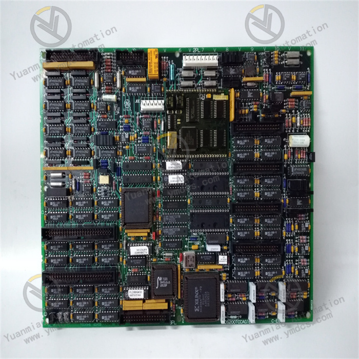
GE VMIACC-5595-208 350-805595-208L
The GE VMIACC-5595-208 350-805595-208L is an industrial control component. Its core positioning is a signal processing and execution control unit in mid-to-high-end industrial control systems, mainly applied in scenarios such as precision control of industrial production lines, motion adjustment of large-scale equipment, and closed-loop parameter control in process industries.
This component receives command signals from a host computer or controller, drives the actuator to operate after internal signal processing, and simultaneously collects the status of the execution end in real time to feed back to the control system, forming a control closed loop of "command reception - processing - execution - feedback". With industrial-grade stability, precise control accuracy, and good compatibility, it is commonly used in fields with strict requirements for control reliability, such as automobile manufacturing, metallurgical rolling, and chemical reaction control. It is a key component to ensure the precise and stable operation of industrial production processes.
- Supports dual-signal control of analog and digital quantities. The analog control accuracy is ±0.1% of full scale, and the digital control resolution reaches 16 bits.
- The control response time is ≤1ms, which can quickly respond to host computer commands and adapt to high-speed motion control or dynamic parameter adjustment scenarios.
- Equipped with PID closed-loop control function, the proportional band, integral time, and derivative time can be flexibly configured to meet the adjustment needs of different controlled objects.
- Input signals: Support 4-20mA DC current signals, 0-10V DC voltage signals, and switching signals (DC 24V).
- Input impedance: ≤250Ω for current signals, ≥10MΩ for voltage signals, and ≥1kΩ for switching signals.
- Output signals: Support 4-20mA current output (load capacity ≤500Ω), 0-10V voltage output (load capacity ≥1kΩ), and relay contact output (rated current 2A/AC 250V).
- Can directly drive executive or indicating equipment such as solenoid valves, servo drives, and indicator lights.
- Adopts a wide-range AC power supply design, suitable for a supply voltage of 208V AC (±10%), and adaptive to 50/60Hz frequency.
- Equipped with an RS-485 communication interface, supports the Modbus-RTU communication protocol, and can realize data interaction with a host computer or PLC.
- The communication rate supports adjustable rates such as 9600bps and 19200bps, and the communication distance is ≤1200 meters.
- Some models may support Ethernet communication (e.g., Modbus/TCP) to adapt to distributed control systems.
- Operating temperature: -20℃ ~ 65℃; Storage temperature: -40℃ ~ 85℃.
- Relative humidity: 5% ~ 95% (non-condensing).
- Vibration resistance rating: IEC 60068-2-6 (10Hz ~ 500Hz, acceleration 5g).
- Shock resistance rating: IEC 60068-2-27 (peak acceleration 15g, duration 11ms).
- Protection rating: IP20 (panel mounting), suitable for installation in industrial control cabinets.
- External dimensions: Approximately 140mm × 100mm × 60mm; adopts standard DIN rail or panel mounting.
Based on the design concept of GE industrial control products and the positioning of this component, it is inferred that the VMIACC-5595-208 350-805595-208L has the following core functional features, aiming to meet the needs of precise control and stable operation in industrial scenarios:
- Simultaneously supports the reception and processing of analog and digital control signals. The control mode can be selected according to the characteristics of the controlled object. For example, 4-20mA analog control is used for the speed adjustment of servo motors, and switching control is used for equipment start-stop.
- Multiple signal types are available at the output end, which can adapt to different types of actuators without additional adapter modules, reducing the complexity of system integration.
- Built-in high-performance PID control algorithm, supports independent adjustment of proportional (P), integral (I), and derivative (D) parameters, and is equipped with a self-tuning function. It can optimize PID parameters by automatically detecting the characteristics of the controlled object, solving the problem that traditional manual adjustment is difficult to adapt to complex working conditions.
- The control accuracy of ±0.1% ensures that controlled parameters (such as temperature, pressure, and speed) are stable at the set value, reducing parameter fluctuations in the production process.
- Adopts dual anti-interference measures of "photoelectric isolation + electromagnetic shielding". The isolation voltage between input/output signals and power supply/communication circuits is ≥250V AC, and the Common Mode Rejection Ratio (CMRR) is ≥120dB@50Hz, which can effectively resist electromagnetic interference generated by equipment such as inverters and motors in industrial fields.
- The wide-range power supply design adapts to grid voltage fluctuations in different regions, ensuring stable operation even in scenarios with unstable voltage.
- Built-in overcurrent, overvoltage, and overtemperature protection functions. When the output load is short-circuited, the power supply voltage is abnormal, or the component temperature exceeds 70℃, it automatically cuts off the output and triggers a fault alarm.
- On-board LED status indicators (power, operation, fault, communication) clearly display the working status. Combined with the communication interface, fault codes can be read remotely to quickly locate the cause of faults and reduce operation and maintenance costs.
As an intermediate execution and processing unit in the industrial control system, the core workflow of the VMIACC-5595-208 350-805595-208L revolves around "signal reception - processing - execution - feedback", and collaborates with the upper control system to realize closed-loop control. The specific links are inferred as follows:
- Complete parameter configuration through host computer software or the DIP switches of the component itself, including control mode (analog/digital), PID parameters (proportional band, integral time, etc.), communication parameters (baud rate, address), and protection thresholds (overcurrent, overvoltage values).
- The component automatically completes initialization after power-on, detects the status of the power supply, communication interface, and output circuit, and lights up the fault indicator if there is an abnormality.
- After the control command signals issued by the host computer or PLC (such as 4-20mA current signals or DC 24V switching signals) are connected through the input interface, they first pass through the photoelectric isolation circuit to suppress interference, and then the internal signal conditioning circuit converts the signals into standard level signals.
- For analog control, the conditioned signals are sent to the PID control unit for comparison and calculation with feedback signals, and adjustment signals are output; for digital control, execution commands are directly generated.
- The processed control signals are amplified by the output drive circuit to drive the actuator (such as servo drive, solenoid valve) to operate.
- At the same time, the component collects the feedback signals of the actuator (such as motor speed pulse signals, valve opening feedback signals), processes them, and uploads them to the host computer through the communication interface to realize real-time monitoring of the control effect.
- If the deviation between the feedback signal and the set value exceeds the threshold, the PID unit automatically adjusts the output signal until the deviation is reduced to the allowable range.
- Real-time monitoring of output current, power supply voltage, and internal temperature of the component. When it is detected that the output current exceeds 1.5 times the rated value, the power supply voltage is outside the range of 208V±15%, or the temperature is ≥70℃, the protection mechanism is triggered immediately: cut off the output circuit, record the fault code, and report it through the fault indicator and communication interface.
- After the fault is eliminated, the component needs to be restored to normal operation through a host computer command or restart.
Combined with the common fault scenarios of industrial control components and the characteristics of this component, the possible typical faults and practical troubleshooting methods are inferred as follows. For actual fault handling, refer to the GE official fault diagnosis manual:
- Possible Causes: Broken power supply line, abnormal power supply voltage (no 208V AC connected), poor contact of the component power interface, faulty internal power circuit.
- Troubleshooting:① Use a multimeter to detect the voltage of the power supply line, confirm whether it is 208V AC±10%, and check the power grid or transformer if the voltage is abnormal.② Power off, re-plug the power connection to ensure tight interface contact, and check if the terminal is loose.③ Test with a spare power cable; if the power indicator still does not light up, the internal power circuit of the component is faulty and needs to be returned to the factory for repair.
- Possible Causes: Control signal not connected or wrong wiring, incorrect control mode configuration (e.g., analog command connected to digital input terminal), broken output circuit or faulty load, faulty component output circuit.
- Troubleshooting:① Use a multimeter to detect the control signal at the input terminal, confirm that the analog signal is 4-20mA/0-10V or the digital signal is DC 24V, and check if the wiring corresponds to the correct terminal.② Verify the component control mode configuration to ensure it matches the input signal type.③ Disconnect the load, detect the signal at the component output terminal; if there is a signal, the load is faulty (e.g., short circuit, burnout); if there is no signal, the component output circuit is faulty.
- Possible Causes: Unreasonable PID parameter configuration, interference with control signals, abnormal feedback signals, excessive load fluctuation.
- Troubleshooting:① Enable the component self-tuning function to allow the component to automatically optimize PID parameters; if the self-tuning effect is poor, manually fine-tune the proportional band (increasing it can enhance stability) and integral time (increasing it can reduce overshoot).② Check if the control signal and feedback signal cables are far from inverters and high-voltage cables; if necessary, cover them with metal shielding tubes and ground them.③ Detect whether the feedback signal is stable; if the feedback signal fluctuates, the sensor is faulty and needs to be replaced.
- Possible Causes: Broken communication cable or poor contact, mismatched communication parameters (wrong baud rate, address), faulty host computer communication port, faulty component communication circuit.
- Troubleshooting:① Use a multimeter to detect the continuity of the communication cable, re-plug the connection to ensure tight contact.② Verify the communication parameters (baud rate, data bits, stop bits, address) of the component and the host computer to ensure they are completely consistent.③ Connect the communication cable to the spare host computer port for testing; if the interruption still occurs, the component communication circuit is faulty and needs to be repaired.
![]()