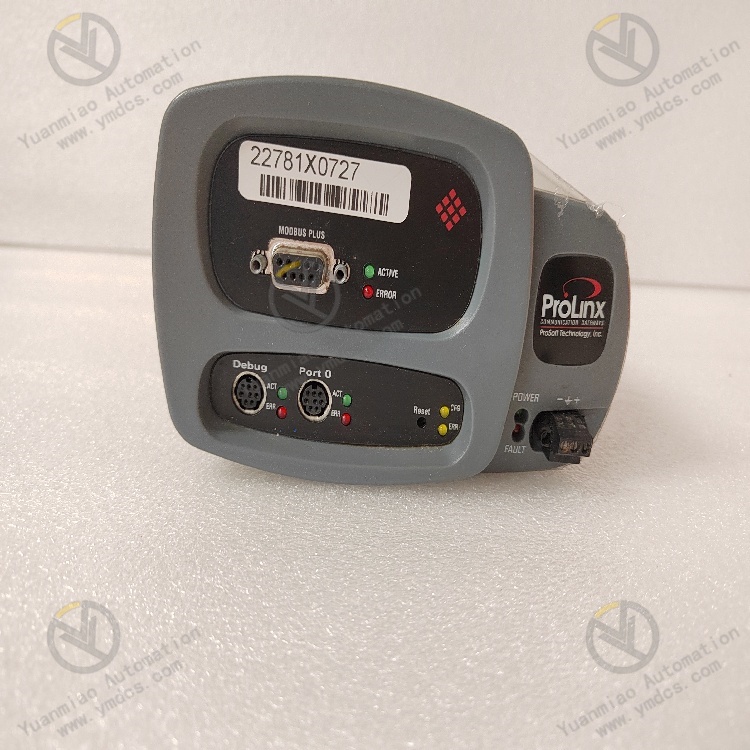
Description
GE Multilin 369-HI-0-0-0-0
The GE Multilin 369-HI-0-0-0-0 is a high-performance integrated motor protection relay specifically designed for medium-voltage and high-voltage (rated voltage ≤ 20kV), medium-power and high-power (rated power ≥ 2MW) asynchronous motors, synchronous motors, and critical rotating equipment. Positioned as the "core terminal for full-operating-condition protection and intelligent monitoring of medium-voltage and high-voltage motors", its core value lies in achieving precise protection throughout the entire lifecycle of motor startup, operation, and shutdown through high-precision electrical parameter collection, multi-dimensional fault diagnosis algorithms, and rapid protection response mechanisms. Meanwhile, it integrates functions such as real-time monitoring, data recording, communication interaction, and basic health diagnosis, providing reliable safety guarantees and operation & maintenance support for key equipment in fields like electric power, petrochemicals, metallurgy, and building materials—including fans, water pumps, compressors, and auxiliary motors for steel rolling.
With core advantages of "precise protection, reliable operation, flexible adaptation, and convenient operation & maintenance", this relay is highly aligned with the operational requirements of medium-voltage and high-voltage motors, such as high load, frequent startup/shutdown, and complex working conditions. It serves as a key component for the closed-loop management of "fault early warning-rapid handling-data tracing" in industrial motor control systems. It performs excellently in key industry scenarios:
- In the electric power sector, it is used to protect induced draft fans and forced draft fan motors in thermal power plants. It can accurately identify hidden faults such as rotor bar breakage and uneven air gaps, issue early warnings more than 15 days in advance, and reduce the unplanned shutdown rate by 40%.
- In the petrochemical sector, it is adapted for circulating water pump motors in refining and chemical units. Through enhanced sealing design and anti-interference circuits, it ensures the reliability of protection actions in high-humidity and dusty environments, with an action accuracy of ≥ 99.5%.
- In the metallurgical sector, it provides comprehensive protection (against overload, short circuit, grounding, etc.) for auxiliary drive motors in steel rolling production lines. It is suitable for frequent startup/shutdown conditions (5-8 times per hour) with a protection accuracy error of ≤ ±1%.
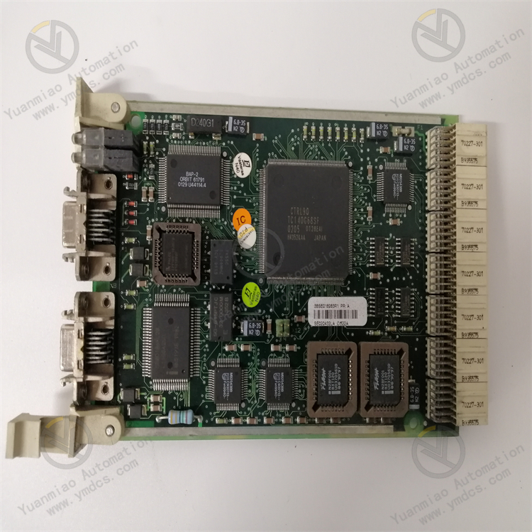
The hardware architecture adopts a high-performance design of "dual-core processor + high-precision collection + redundant backup". Its core consists of a 32-bit dual-core industrial-grade processor, a 20-bit high-precision A/D sampling chip, 8 independent protection output interfaces, and a multi-protocol communication module. It is equipped with 4-phase current input channels (compatible with programmable CT ratios from 1:1 to 1:10,000, supporting CT open-circuit detection), 3 voltage input channels (compatible with multiple voltage levels of 100V/220V/400V), 12 digital input channels (including 2 high-speed DIs with a response time of ≤ 2μs), and 8 relay output channels (with a capacity of AC250V/8A and DC24V/12A, supporting custom functions such as tripping, alarming, and interlock control). It has built-in dual communication interfaces (RS485 and EtherNet/IP), enabling seamless integration with mainstream monitoring systems such as GE CIMPLICITY and Siemens WinCC. Its protection functions cover more than 20 types of motor faults, including overload (optional inverse time/definite time), short circuit (instantaneous trip/delayed instantaneous trip), grounding (zero-sequence current/residual current), locked rotor, phase loss, under-voltage/over-voltage/voltage unbalance, rotor bar breakage, winding temperature, and bearing temperature. It supports custom logical interlock relationships via configuration software. The industrial-grade reinforced design uses industrial-grade wide-temperature components (-40℃~75℃), a single-layer metal shielded enclosure (shielding effectiveness ≥ 85dB), and enhanced anti-electromagnetic interference circuits. It complies with international standards such as IEC 61850-3 and IEC 60255-22, and can operate stably in industrial sites with strong electromagnetic interference, high dust, high humidity, and high altitude (≤ 4,000m).
A dual-dimensional precise protection system of "electrical quantities + temperature quantities" is built to adapt to the multi-operating-condition requirements of medium-voltage and high-voltage motors.
- In terms of electrical protection: It adopts 192-point/cycle high-precision sampling and dual-core processor parallel computing, with a short-circuit protection action time of ≤ 10ms, which can quickly cut off short-circuit faults in 20kV systems and effectively reduce the impact damage of faults on motor stator windings. The overload protection supports the inverse time characteristic specified in IEC 60255-3, with multiple built-in motor heating models. It can dynamically adjust the action curve according to the motor load type (constant torque, variable torque) to avoid false tripping under light load and failure to trip under heavy load.
- In terms of temperature protection: 6 high-precision temperature input channels can simultaneously monitor the temperatures of key parts such as stator windings and front/rear bearings. It supports a dual-alarm mechanism of temperature set-value alarm and temperature rise rate alarm. When the temperature exceeds the threshold or the temperature rise rate is ≥ 8℃/min, it issues alarm, load reduction, and tripping commands in sequence to prevent accelerated aging of motor insulation.
- The rotor bar breakage protection is based on current spectrum analysis technology, extracting fault characteristic frequencies through the FFT algorithm, with a bar breakage detection accuracy of ≥ 0.3%. It can capture hidden faults of the motor rotor in advance, reserving sufficient processing time for operation & maintenance personnel.All protection parameters support software configuration, with an action threshold adjustment accuracy of ±0.5%, adapting to the protection needs of different models of medium-voltage and high-voltage motors.
A triple-reliability design of "anti-interference + wide temperature range + sealing" is adopted to ensure stable operation in complex industrial environments.
- In terms of anti-interference design: The enclosure uses a single-layer metal shielding structure, and copper foil shielding layers are laid on key internal circuits. A complete shielding network is formed through multi-point grounding, with a shielding effectiveness of ≥ 85dB, complying with the IEC 61000-4-3 radio frequency radiation immunity standard (10V/m). It can resist strong electromagnetic interference generated by the opening and closing of circuit breakers in high-voltage switchgear. The signal input circuit adopts photoelectric isolation technology with an isolation voltage of ≥ 3kVrms, effectively blocking common-mode interference and differential-mode interference to avoid equipment damage caused by on-site high-voltage signal impact. The power supply circuit is equipped with a two-stage EMC filter to filter out power grid harmonics and pulse interference. When the power supply voltage fluctuates in the wide range of 85V~265V, the output voltage stability is ±0.8%.
- In terms of wide-temperature and sealing design: Industrial-grade wide-temperature components (-40℃~75℃) are selected, combined with an intelligent heat dissipation air duct design, ensuring stable operation in high-cold areas in Northeast China and high-temperature workshops in South China. The enclosure adopts an IP45 protection level sealing design, effectively preventing dust and moisture intrusion, and is suitable for dusty and high-humidity scenarios such as petrochemicals and metallurgy.The equipment has an MTBF of ≥ 300,000 hours, meeting the reliability requirements of long-term operation of medium-voltage and high-voltage motors.
High-precision measurement and massive data recording functions are integrated to provide data support for operation & maintenance management.
- In terms of measurement: A 20-bit high-precision A/D sampling chip realizes precise measurement of parameters such as current, voltage, power, and frequency. The current and voltage measurement accuracy is ±0.15% FS, and the power measurement accuracy is ±0.3% FS, meeting the requirements of electric energy metering level and directly replacing traditional electrical quantity transmitters.
- In terms of data recording: It can store 150 fault oscillography records, each containing complete electrical parameter waveforms of 15 cycles before the fault, 8 cycles during the fault, and 20 cycles after the fault, with a sampling resolution of 1ms, providing accurate data for fault cause analysis. 800 event records cover key events such as protection actions, parameter modifications, and communication interruptions, with a timestamp accuracy of ±1s, facilitating the tracing of equipment operation history.It supports data export and remote monitoring functions. Historical data can be exported to CSV format through a USB interface or EtherNet/IP network, and waveform analysis and trend statistics can be performed with GE EnerVista software. Remote functions such as protection parameter configuration, real-time data collection, and fault diagnosis can be realized, allowing operation & maintenance personnel to complete equipment debugging and fault troubleshooting without on-site presence, improving operation & maintenance efficiency by more than 50%.
It has adaptive integration capabilities of "wide range + multi-protocol + easy configuration", compatible with system requirements of different scenarios.
- In terms of range adaptation: The current measurement range is 0.1A~15kA (via CT), and the voltage measurement range is 20V~20kV (via PT), supporting parameter collection for medium-power and high-power motors above 2MW, and adapting to motor systems with different voltage levels from 6kV to 20kV.
- In terms of protocol compatibility: It supports multiple communication protocols such as Modbus RTU, Modbus TCP, and IEC 61850, enabling seamless integration with monitoring systems of different manufacturers such as GE, Siemens, and Schneider, realizing centralized monitoring of motor operation status.
- In terms of configuration: It supports GE EnerVista configuration software, with built-in standardized function blocks (AND gate, OR gate, timer, etc.). Custom protection logic and control circuits can be implemented through drag-and-drop programming without writing complex code, adapting to different control scenarios such as single-machine operation and multi-machine linkage.The panel is equipped with a 240×128 dot-matrix LCD display, supporting bilingual display (Chinese/English), which can display motor operation parameters, protection status, and fault information in real time. Common parameters can be directly modified via operation buttons, improving the convenience of on-site operation.
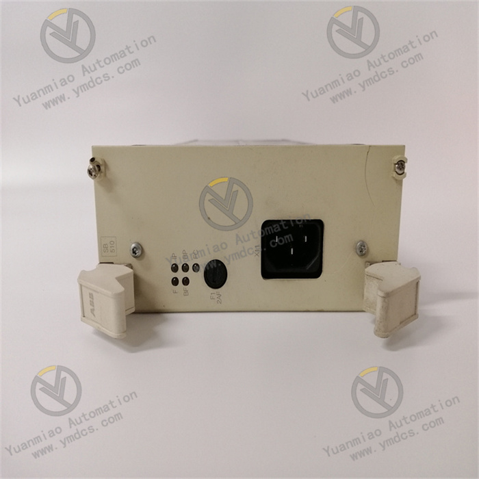
- Verify that the equipment model is GE Multilin 369-HI-0-0-0-0, with no collision deformation on the appearance and no oxidation or rust on the terminals. Check that parameters such as CT/PT ratio range and power supply voltage level are compatible with the equipment according to the design documents.
- The installation environment shall meet the conditions of temperature -40℃~75℃ and humidity 5%~95% (no condensation). Keep away from strong interference sources such as high-voltage busbars (distance ≥ 400mm) and frequency converters (distance ≥ 200mm), and avoid direct sunlight and rain erosion. Reserve a heat dissipation space of ≥ 80mm at the installation location to ensure good ventilation.
- Prepare special tools: torque screwdriver (0.5~1.5N·m), 500V insulation resistance tester, high-precision multimeter (accuracy ≥ 0.01%), debugging computer pre-installed with GE EnerVista software, standard signal source. For high-voltage scenarios, safety equipment such as insulating gloves and electroscopes shall be prepared.
- Installation personnel shall have the qualification for installing medium-voltage and high-voltage electrical equipment and strictly implement the safety procedure of "power-off → electroscope → grounding". For panel-embedded installation, the opening size shall be 165×165mm (tolerance ±1mm), and the torque of the fixing screws shall be 1.2N·m to avoid damaging the enclosure due to excessive tightness. For drawer-type installation, ensure the guide rail levelness is ≤ 0.8mm/m to ensure smooth insertion and extraction.
- Before wiring, use a 500V insulation resistance tester to test the insulation resistance of the input circuit (≥ 10MΩ) and power supply circuit (≥ 50MΩ). Use shielded twisted-pair cables with a cross-sectional area of ≥ 2.5mm² for the current circuit, and ground one end of the shielding layer (grounding resistance ≤ 1Ω). Separate the voltage circuit from the current circuit during wiring (distance ≥ 150mm) to avoid cross-interference.
- During wiring, strictly distinguish between current, voltage, digital input, and relay output terminals according to the wiring diagram to avoid equipment damage caused by wrong connection. The secondary side of the CT is strictly prohibited from being open-circuited
![]()