Description
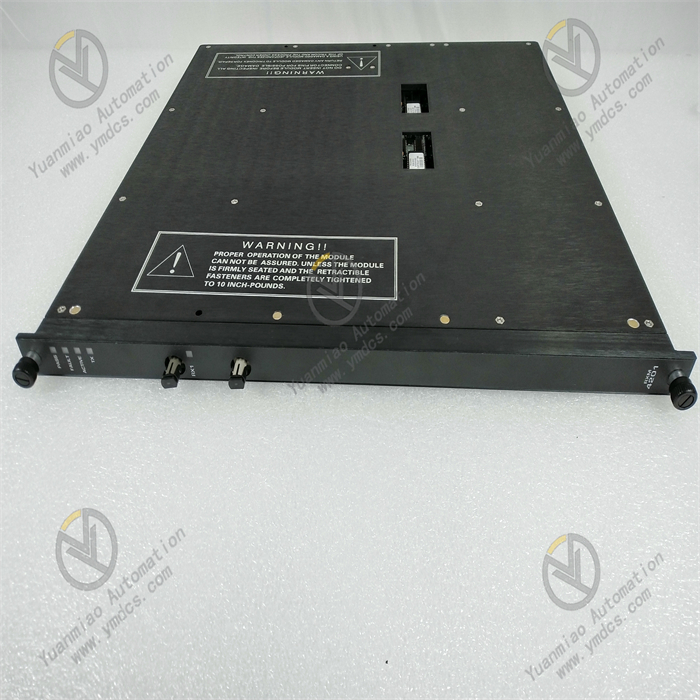
ICS Triplex TC-305-01-5M0 is part of a triple redundant control system. It adopts a unique Triple Modular Redundancy (TMR) architecture. Through triple processing of input, processing, and output, it can maintain the normal operation of the system even when a single module fails, greatly improving the reliability and safety of the system. Technical Parameters Power Supply Requirements: Generally, it supports a wide range of DC power input, commonly such as 24V DC ±15%, to adapt to different industrial power supply environments. Communication Interfaces: It is usually equipped with multiple communication interfaces. For example, the Ethernet interface is used for high-speed data communication and data exchange with other devices or systems; serial communication interfaces such as RS-485 are used for connecting and communicating with specific devices. Processing Capacity: It has a powerful processing capacity and can quickly process a large amount of input and output data and complex control logic. Its processor is fast, enabling real-time control and monitoring functions. I/O Characteristics: As an input and output module, it may support various types of input and output signals, such as digital input and output (used for controlling switch states, etc.) and analog input and output (used for processing continuously changing signals such as temperature, pressure, etc.). The specific number and types of I/O points will vary according to different configurations. Operating Temperature Range: It can work in relatively harsh industrial environments. Generally, the operating temperature range is from -40°C to 70°C, which can adapt to different industrial field environments.
Product Features High Reliability: Based on the TMR architecture, it can automatically detect and isolate faulty modules, ensuring that the system can still operate reliably in case of failures and reducing the risk of system downtime. Fault Tolerance: Even if a certain module fails, the system can still continue to operate normally, and the faulty module can be replaced and repaired online without affecting the operation of the system. Flexibility: It supports multiple programming languages and development tools, making it convenient for engineers to program and configure to meet different industrial control requirements. At the same time, I/O points and functions can be increased through expansion modules, and it has strong expandability. Safety: It complies with strict industrial safety standards and can be used in application scenarios with extremely high safety requirements, such as the petrochemical, power, and nuclear power industries. It can effectively prevent accidents and protect the safety of personnel and equipment. Application Scenarios Petrochemical Industry: It is used for the control and monitoring of key equipment, such as distillation towers in refineries and reactors in chemical plants, to ensure the safe and stable operation of the production process. Power Industry: In the control system of power plants, it is used for the protection and control of generator sets, the dispatching and management of the power grid, etc., to improve the reliability and stability of the power system. Nuclear Power Industry: As part of the safety system of nuclear power plants, it is used for monitoring and controlling the operating parameters of the reactor to ensure the safe operation of the nuclear power plant. Other Industries: Such as the metallurgical, pharmaceutical, food and beverage industries, etc., it is used for precise control and monitoring of the production process to improve production efficiency and product quality.
General Installation and Debugging Steps of ICS Triplex TC-305-01-5M0: Installation Steps 1. Preparation before Installation: Confirm that the module model matches the system to be installed, and check whether the appearance of the module is damaged and whether all components are complete. Prepare the tools required for installation, such as screwdrivers, wrenches, etc. Ensure that the installation environment meets the requirements. The ambient temperature should be within the specified operating temperature range of the module from -40°C to 70°C, the humidity should be appropriate, there should be no severe vibration, no corrosive gases, and there should be good ventilation. Understand the electrical layout and topology of the system and determine the installation location of the module. 2. Electrical Connection: Connect the power input of the module according to the electrical schematic diagram of the system. Ensure that the connected power supply voltage is the rated 220V of the module and the polarity is correct to prevent damage to the module due to reverse connection. Connect the communication lines between the module and other devices (such as controllers, sensors, actuators, etc.). According to the type of communication interface (such as Ethernet, RS-485, etc.), use the corresponding cables and ensure that the connections are firm, following the relevant wiring specifications to avoid signal interference. 3. Mechanical Installation: According to the size and installation holes of the module, use suitable screws or fixtures to fix the module on the designated installation plate, control cabinet or rack. Ensure that the module is firmly installed during installation to prevent looseness due to vibration during operation. Pay attention to leaving enough space around the module for heat dissipation and maintenance operations, and avoid being too close to other devices with high heat generation. 4. Grounding Connection: Connect the grounding terminal of the module to the grounding busbar of the system through a dedicated grounding wire to ensure reliable grounding. The grounding resistance should meet the relevant standard requirements, generally not more than 4 ohms, to ensure the safety of equipment and personnel and reduce electrical interference.

Debugging Steps
1. Inspection before Powering On:
Check again whether all electrical connections are correct and firm, especially the power connection and communication lines, to ensure that there are no short circuits, open circuits or loose connections.
Confirm that the grounding connection is good.
2. Powering On and Starting:
Close the power switch to power on the module. Observe whether the power indicator on the module lights up normally. If the indicator does not light up, cut off the power immediately and check whether there are faults in the power connection and the module.
3. Parameter Configuration:
Connect to the module using the corresponding configuration tools (such as programming software, human-machine interface, etc.).
According to the actual application requirements, configure the parameters of the module, such as the types, ranges, and filtering parameters of input and output signals, communication parameters (such as IP address, baud rate, communication protocol, etc.), and parameters related to the control logic, etc. The configuration of these parameters usually needs to refer to the technical manual of the module and the specific application scenarios.
4. Function Testing:
Conduct input signal testing. By simulating the actual input signal source (such as sensor signals), check whether the module can correctly receive and process the input signals, and check whether the display and status of the input signals on the configuration tool or monitoring interface are consistent with the actual input.
Conduct output signal testing. Send output commands through the configuration tool or control logic, check whether the module can correctly output the corresponding signals, drive the external actuators (such as relays, valves, etc.) to act, and observe whether the actions of the actuators meet the expectations.
Test the communication function of the module, conduct data exchange tests with other related devices, and check whether data can be normally received and sent, and whether the accuracy and timeliness of the data meet the requirements.
5. System Joint Debugging:
Integrate the module into the entire industrial automation system and conduct joint debugging with other devices and systems.
Check whether the collaborative work between the module and other devices is normal in the actual industrial control process, whether the control logic is correctly implemented, and whether it can meet the requirements of the production process.
During the joint debugging process, it may be necessary to further optimize and adjust the parameters of the module according to the actual situation.
6. Stability Testing:
After the system has been operating normally for a certain period of time (such as several hours or days), observe the operating status of the module, including whether the temperature, power supply voltage, signal transmission, etc. are stable, and whether there are any abnormal alarms or faults.
Check whether the module can respond promptly and accurately to various changes in input signals during long-term operation, and whether the control effect is stable and reliable.