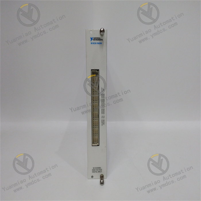
Description
GE IS230TNTRHIC
I. Overview
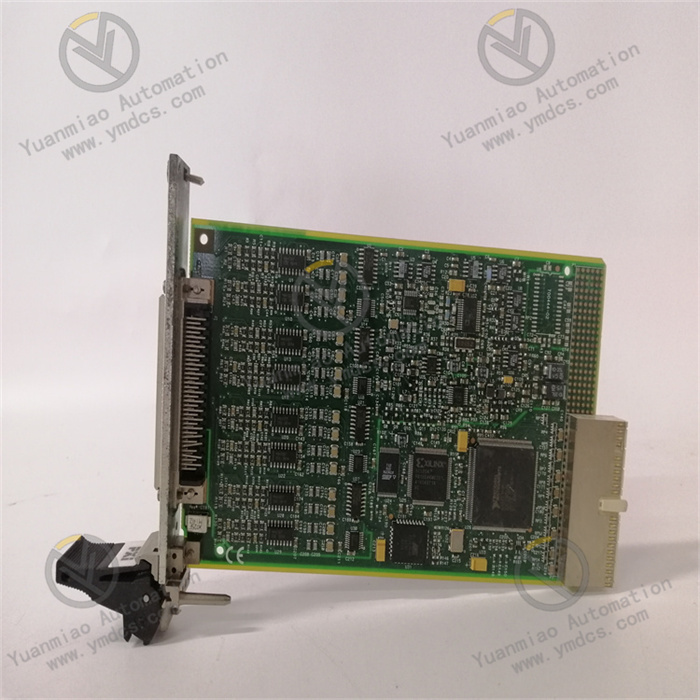
The GE IS230TNTRHIC is a high-performance terminal signal conversion and control module, serving as a critical interface component that connects on-site turbine instruments to the main controller. Its core value lies in providing an integrated solution for large rotating machinery such as gas turbines and steam turbines, encompassing "speed signal acquisition, digital-to-analog conversion, main protection execution, and excitation regulation adaptation". Acting as the "signal translator" and "execution commander" for unit control, it enables real-time monitoring of key parameters (e.g., turbine speed, generator voltage) and precise actuation of executive components (e.g., fuel valves, main circuit breakers) through "multi-type signal compatibility, high-precision conversion, and redundant control design". It meets the stringent requirements of the power and oil & gas industries for turbine start-stop, load adjustment, and safety protection, and is a core control unit ensuring reliable unit operation.
This module adopts an industrial-grade conformal coated PCB design, supports Triple Modular Redundancy (TMR) configuration for the Mark VIe system, and enables signal parameter calibration and protection logic configuration when used with ControlST programming software. It is widely applied in global large-scale turbine control fields, especially suitable for turbine main control loops requiring high safety redundancy.
II. Technical Specifications
(I) Core Signal Processing and Conversion Parameters
1. Input/Output Channel Configuration
Dedicated Input Channels
- Speed Signal Input: 4-channel TTL level speed sensor interface (compatible with magnetoelectric MPU sensors), with a frequency range of 2Hz-20kHz, sensitivity of 27mV peak, accuracy of ±0.05% pulse rate, suitable for turbine main shaft speed monitoring;
- Electrical Parameter Input: 2-channel generator voltage/current signal input (0-10V DC or 4-20mA), 16-bit resolution, accuracy of ±0.05% FS, used for excitation system voltage feedback;
- Logic Input: 8-channel non-potential dry contact inputs (powered by 125V DC, power consumption of 12mA), suitable for emergency stop buttons and interlock protection contact signals.
Output Channels
- Analog Output: 4-channel configurable analog outputs (switchable between 4-20mA/0-10V DC), load impedance ≤500Ω, 14-bit resolution, accuracy of ±0.1% FS, used to drive fuel control valves and excitation regulators;
- Relay Output: 2-channel 125V DC/0.2A inductive load outputs, driving the relay coils of the main circuit breaker (52G) (e.g., K25, K25P) and supporting forced opening control;
- Channel Isolation: 2500V AC isolation (with 1-minute voltage withstand capability) between input and output channels, and 1500V AC isolation between analog and digital channels. It resists common-mode interference voltage of ±500V DC to prevent crosstalk from high-voltage signals.
2. Signal Conversion and Response Characteristics
- Digital-to-Analog Conversion (DAC) Response: The stabilization time from digital command to analog output is ≤20ms (99% step response), meeting the real-time requirements for fuel adjustment;
- Speed Signal Processing: Built-in hardware filtering and pulse shaping circuits, which can filter out noise signals caused by mechanical vibration. The speed measurement update cycle is ≤1ms;
- Logic Response Time: The response time from emergency stop logic input to relay output action is ≤5ms, meeting the fast-response requirements for turbine safety protection.
(II) Electrical and Environmental Parameters
1. Power Supply and Power Consumption
- Main Power Supply: Dual-channel redundant 125V DC power supply (compatible with 110-140V DC), drawing power from the Mark VIe backplane CEX bus. The rated power consumption of a single module is ≤25W (under full-load output);
- Auxiliary Power Supply: Built-in 24V DC/1A isolated power supply, providing power for external speed sensors and transmitters, with overcurrent protection (automatic cutoff at 1.2A);
- Protection Functions: Power reverse polarity protection, output short-circuit protection (relay output with overload fuse protection), and over-temperature protection (automatic derated output at 65℃).
2. Environmental Adaptability
- Operating Environment: Temperature range of -30℃ to +65℃ (no derating), storage temperature range of -40℃ to +85℃, relative humidity of 5%-95% RH (no condensation);
- Mechanical Protection: The PCB is treated with a conformal coating to resist moisture and corrosion, adapting to dusty and high-humidity environments in turbine control rooms;
- Electromagnetic Compatibility: Passed IEC 61000-4-3 (10V/m RF radiation immunity) and IEC 61000-4-5 (2kV surge immunity) tests, resisting electromagnetic interference from the generator excitation system.
(III) Communication and Redundancy Parameters
1. Communication Interfaces
- Backplane Communication: Communicates with the VTUR control module via the Mark VIe system's CEX high-speed bus (100Mbps), with a data update cycle of ≤5ms, supporting deterministic control signal transmission;
- Expanded Communication: Standard RS-485 interface (supporting Modbus RTU protocol) and RJ45 Ethernet interface (supporting TCP/IP), which can connect to local HMI or DCS systems. The communication rate is adjustable from 9600 baud to 100Mbps;
- Diagnostic Communication: Built-in intelligent diagnostic chip, which can report channel faults, power status, communication link quality, and other information, supporting remote parameter calibration and fault reset.
2. Redundancy and Reliability
- Redundancy Support: Supports Triple Modular Redundancy (TMR) configuration, where 3 modules operate in parallel and output control signals through majority voting logic, with no impact from single-point faults. It can also be configured in simplex mode to meet the needs of non-critical loops;
- Reliability Index: Mean Time Between Failures (MTBF) ≥120,000 hours, complying with SIL 3 safety level (IEC 61508) and supporting online hot-swap replacement.
III. Functional Features
(I) Multi-Signal Integration and Processing, Simplifying Control Architecture
It integrates multi-dimensional functions such as speed monitoring, electrical parameter acquisition, analog output driving, and relay execution, and can replace the traditional combined solution of "speed module + analog output module + relay module". For example, in gas turbine control, this module can simultaneously realize:
- Acquisition: Main shaft speed (MPU sensor signal), generator terminal voltage (4-20mA), emergency stop contact (dry contact);
- Conversion and Output: Convert speed signals into digital quantities and upload them to the controller, convert controller commands into 4-20mA signals to drive fuel control valves, and trigger relays to control the opening of the main circuit breaker;
Compared with discrete modules, it reduces installation space and wiring workload by 60% and lowers system integration complexity.
(II) High-Precision Speed Measurement, Ensuring Speed Regulation Stability
The signal processing circuit is optimized for turbine speed control needs, enabling accurate capture of wide-range speed signals (2Hz-20kHz) with a measurement accuracy of ±0.05% pulse rate. During the gas turbine speed-up process, the module collects speed signals in real-time and uploads them to the controller. The controller generates adjustment commands via the PID algorithm, and the module then converts these commands into analog signals to drive the fuel valve, achieving precise control of the speed-up rate (±5rpm/s) and avoiding unit vibration caused by speed overshoot or fluctuation.
(III) Redundant Design and Fast Response, Enhancing Safety Protection
It supports TMR redundancy configuration and millisecond-level fault response, meeting the "zero-delay" requirement for turbine safety protection. During steam turbine operation, if the module detects that the speed exceeds 110% of the rated value, the logic input channel receives the overspeed protection signal and triggers the relay output to cut off fuel supply and open the main circuit breaker in only 5ms. Even if a single module fails, the TMR redundancy architecture can automatically shield the fault signal through majority voting, ensuring no interruption of the protection logic and shortening the unit's emergency shutdown response time to ≤100ms.
(IV) Multi-Protocol Compatibility, Enabling Cross-System Collaboration
With a dual-communication design featuring RS-485 and Ethernet interfaces, it can seamlessly connect to the Mark VIe main controller, DCS system, and local operation terminal. In a combined cycle power plant, the module transmits real-time control signals with the VTUR controller via the CEX bus on one hand, and uploads operating parameters such as speed and voltage to the DCS via the Modbus RTU protocol on the other hand. Meanwhile, it receives remote start-stop commands from the DCS, realizing collaborative management of "local precise control + remote centralized monitoring". When used with ControlST software, it enables remote calibration of analog output accuracy, reducing on-site commissioning workload.
IV. Application Fields
(I) Power Industry: Main Control of Gas/Steam Turbines
Gas Turbine Speed and Load Control
The module collects the main shaft MPU speed signal (2Hz-20kHz), converts the controller's load command into a 4-20mA signal to drive the fuel control valve, and achieves rated speed control of 3000rpm (50Hz) with a load adjustment accuracy of ±0.5% rated power. At the same time, it controls the opening and closing of the main circuit breaker 52G via relay output, enabling unit grid connection and disconnection operations.
Steam Turbine Overspeed Protection
Three modules are configured to form a TMR redundancy system for real-time speed signal monitoring. When the speed exceeds 112% of the rated value, all three modules simultaneously trigger the relay output to cut off the steam inlet valve, realizing triple redundancy protection and preventing overspeed runaway accidents.
(II) Oil & Gas Industry: Control of Compressor-Driving Turbines
Speed Regulation of Natural Gas Compressor Units
The module collects the speed signal of the driving turbine, performs integrated processing of the compressor outlet pressure feedback (0-10V) and speed signal, and outputs a 4-20mA signal to adjust the opening of the fuel gas valve. It achieves stable control of the outlet pressure (±0.1MPa), meeting the pressure regulation requirements of long-distance natural gas pipelines.
Turbine Excitation System Adaptation
It sends a voltage setpoint signal (4-20mA) to the excitation regulator via the analog output channel, and collects the generator terminal voltage signal for closed-loop regulation. This ensures the generator output voltage remains stable within the range of 10kV±5%, preventing voltage fluctuations from affecting the operation of the compressor unit.
(III) Industrial Power: Turbine Control in Captive Power Plants
Steam Turbine Control in Biomass Power Plants
The module receives the boiler steam pressure signal (4-20mA), adjusts the steam control valve in combination with speed feedback, and achieves matching control between unit load and steam supply. When the steam pressure is below the threshold, it triggers interlock protection to cut off fuel supply, ensuring unit safety.
Gas Turbine Protection in Waste Incineration Power Plants
It monitors protection signals such as furnace negative pressure and flue gas temperature via logic input channels. When any signal exceeds the limit, it quickly triggers the relay output to execute an emergency shutdown and sends alarm information to the central control room via Ethernet, shortening fault handling time.
V. Selection and Engineering Implementation Recommendations
(I) Selection Criteria
Control Object Matching
It is suitable for turbine main control loops requiring speed monitoring + analog regulation + relay execution. For pure auxiliary loops (e.g., lubrication systems), the more cost-effective IS215 series modules can be selected.
Redundancy Level Requirements
For main control loops requiring SIL 3 safety level, TMR redundancy (3 modules) must be configured; for non-safety loops, simplex mode (1 module) can be adopted.
Signal Type Adaptation
It is preferred for scenarios requiring processing of TTL speed signals, 4-20mA/0-10V analog signals, and dry contact logic signals. For pure digital signal scenarios, dedicated digital modules can be selected.
(II) Peripheral Configuration Recommendations
Sensors and Actuators
- Speed Measurement: Priority is given to GE original magnetoelectric MPU sensors (outputting TTL level);
- Analog Output Driving: 4-20mA proportional control valves (e.g., Fisher DVC6200 series) are selected;
- Relay Output Adaptation: 125V DC small intermediate relays (e.g., Omron G2R series) are used.
Redundancy Matching
For TMR configuration, 3 identical modules are required. The power supply should use the GE IS200PWRCH1A redundant power supply (125V DC/20A); twisted-shielded cables should be used for communication cables (with a cross-sectional area of ≥1.0mm² for analog signal cables).
Wiring Specifications
Speed signal cables should be laid independently, with a distance of ≥500mm from power cables; analog and digital cables should be routed separately, and the shield layer should be grounded at one end (ground resistance ≤0.5Ω).
(III) Installation and Commissioning Notes
Installation Requirements
The module must be installed in a Mark VIe standard control cabinet (e.g., IC698CAB200), away from strong electromagnetic interference sources such as excitation cabinets. The installation spacing should be ≥50mm to ensure good heat dissipation (ambient temperature ≤65℃).
Parameter Configuration
Configure the speed signal frequency range (e.g., 3000rpm corresponding to 50Hz), analog output range (4-20mA corresponding to 0-100% valve position), and protection logic trigger threshold (e.g., speed exceeding 110% of rated value triggering shutdown) via ControlST software.
Commissioning and Verification
- Speed Calibration: Connect standard pulse signals (e.g., 50Hz, 100Hz) and verify that the deviation between the measured value and the standard value is ≤±0.05%;
- Analog Output Test: Input digital commands (0-100%) and measure the output current/voltage values, ensuring the accuracy deviation is ≤±0.1% FS;
- Redundancy Test: Manually disconnect the power supply of one module under TMR configuration, check that the output signal is not interrupted, and confirm that the faulty module can be replaced online with automatic parameter synchronization.


