Description
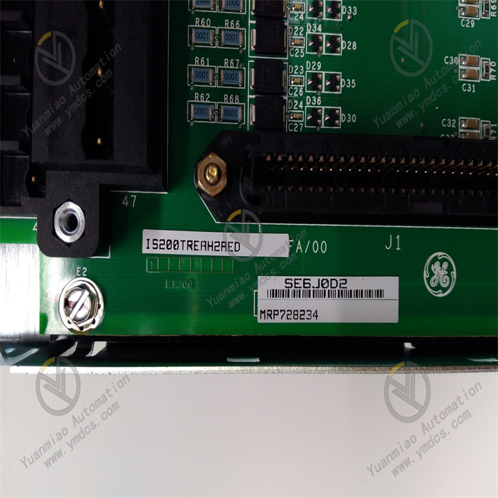
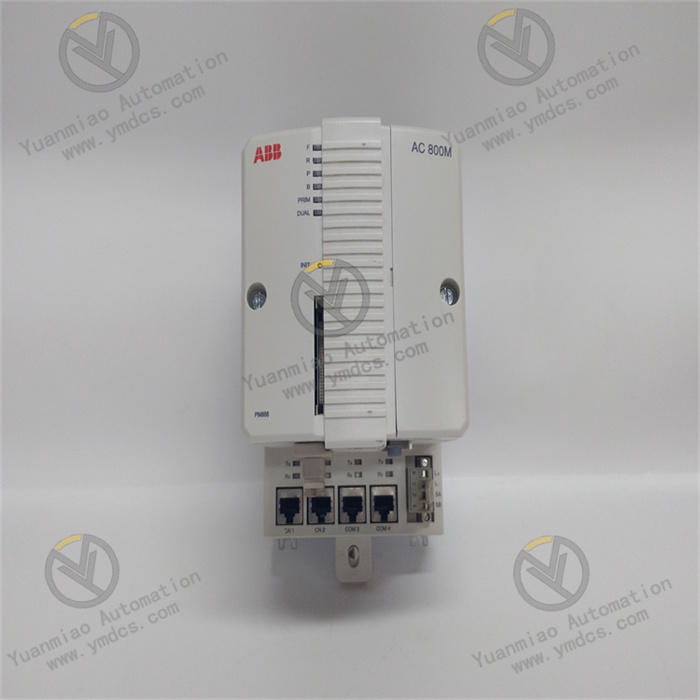
GE IS200TREAH2AED
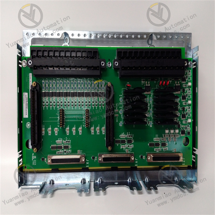
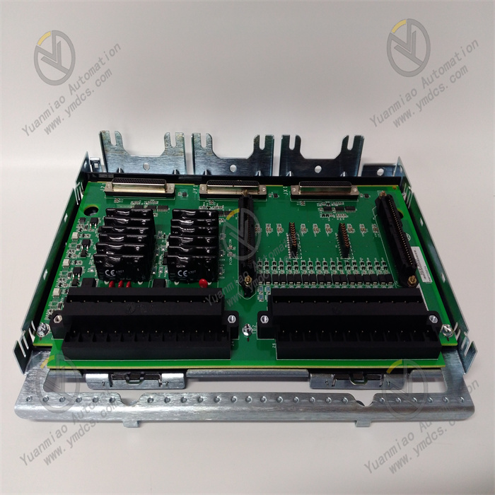
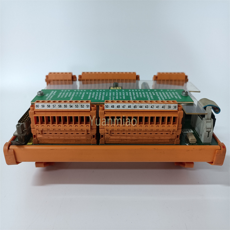
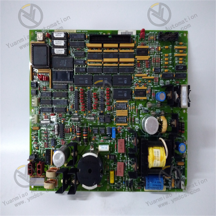
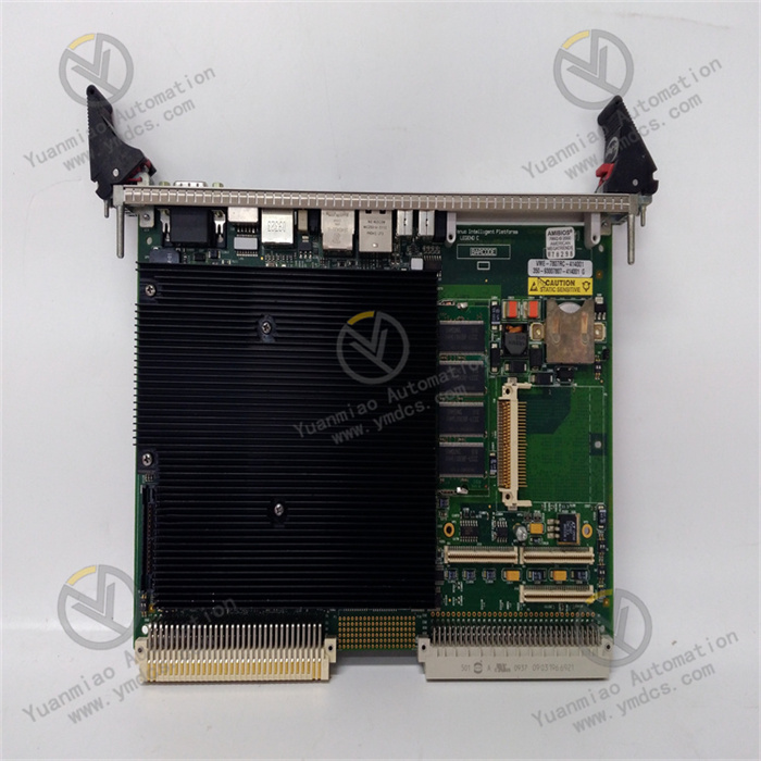
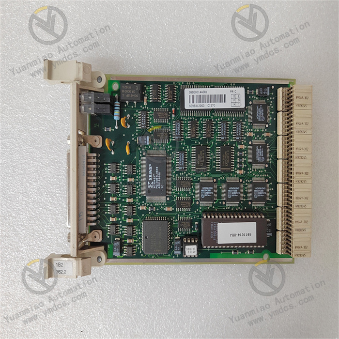
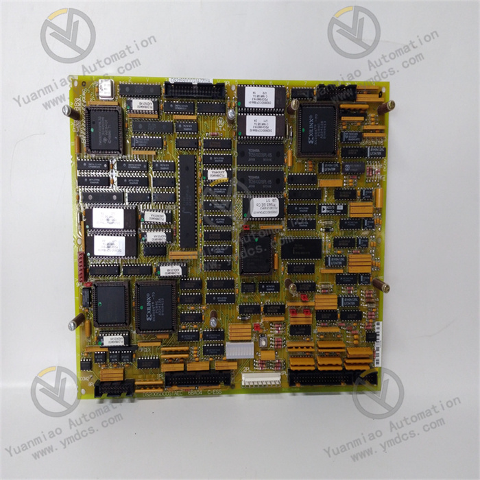
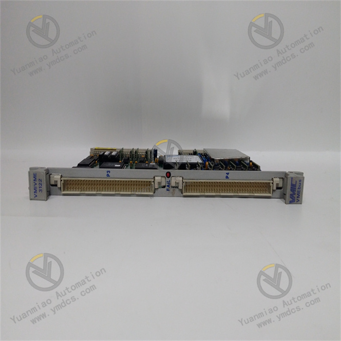
The GE IS200TREAH2AED is a redundant control and signal amplification module belonging to the Mark VIe turbine control system. Its core positioning is a "unit for redundant transmission, power amplification, and anti-interference processing of key turbine control signals". Its core value lies in integrating GE's patented redundant signal synchronization technology and high-power signal amplification technology, providing an integrated solution of "control signal redundant backup + power-enhanced drive + electromagnetic interference suppression" for key actuators of gas turbines and steam turbines (such as fuel valves, steam valves, and emergency shutdown valves).
Compared with general-purpose signal amplification modules, it focuses more on "control safety in turbine scenarios" — it supports redundant transmission and power amplification of 4 channels of analog control signals (4-20mA) (output load capacity ≤1000Ω) and redundant backup of 2 channels of digital emergency control signals (dry contacts). It holds SIL 2 safety certification (IEC 61508) and has the ability to withstand high vibration (≤5g) and high temperature (ambient temperature ≤65℃), enabling stable operation under the harsh working conditions of high electromagnetic interference and high-power loads in turbines. By collaborating with Mark VIe control logic modules (e.g., IS200TBCIH1CCD), it amplifies weak control signals (such as 4-20mA valve commands) into high-power drive signals, while realizing redundant backup of main and standby signals. When the main signal link fails, the redundant link can switch seamlessly within ≤20ms, avoiding equipment shutdown or safety accidents caused by the loss of control of key turbine actuators. It is a key component for "high-safety-level control" of turbine equipment in industries such as power generation, petrochemicals, and aerospace.
As the core signal drive unit of the Mark VIe control system, this module supports seamless integration with GE turbine controllers (TCIA/TCIB) and actuators (e.g., Fisher valve positioners), and is compatible with the Modbus TCP protocol for status monitoring. It balances the safety of turbine control and the flexibility of system integration, providing reliable signal support for "key actuator drive" and "safety interlock" of turbine equipment.
- Main-Standby Hot Redundancy Design: 4 channels of analog control signals and 2 channels of digital interlock signals all support main-standby dual-link input. When the main link fails (e.g., signal disconnection, excessive interference), the redundant link switches seamlessly within ≤20ms, with output signal fluctuation ≤±0.05mA (analog), avoiding the loss of control of key actuators such as turbine valves due to signal interruption (e.g., sudden fuel valve closure causing a sharp load drop).
- Signal Synchronization and Disturbance-Free Switching: Main and standby input signals are calibrated in real time via GE's dedicated synchronization algorithm (synchronization error ≤0.01mA). During switching, the output signal transitions smoothly without step changes (e.g., when switching from a main signal of 20mA to a standby signal of 20.001mA, the output transitions at a rate of 0.001mA/ms), preventing actuator action shocks (e.g., sudden valve opening or closing).
- Real-Time Monitoring of Redundancy Status: Main-standby link status (e.g., "Main Link Normal", "Standby Link Standby", "Link Switch Alarm") is uploaded in real time via LED indicators and the Modbus TCP protocol. Operation and maintenance personnel can remotely monitor the redundant operation status and troubleshoot potential faults in advance (e.g., timely maintenance when the standby link signal deviation exceeds the limit).
- High-Load Drive Capacity: The analog output load capacity is ≤1000Ω (far exceeding the 750Ω of general-purpose modules), enabling direct driving of high-load turbine valve positioners (e.g., impedance of Fisher DVC6200 with long-distance cables) without additional power amplifiers, reducing system complexity.
- High-Precision Linear Amplification: Output accuracy is ±0.1% FS, with a linear error of ≤0.05% relative to the input signal (e.g., an input of 4mA results in an output of 4.000±0.004mA), ensuring turbine valve opening control accuracy (e.g., fuel valve opening error ≤0.1%) and avoiding load fluctuations caused by signal amplification distortion.
- Overload and Short-Circuit Protection: The analog output has overcurrent protection (automatic current limiting to 25mA when >25mA), and the digital output has overcurrent protection (automatic shutdown when >6A), preventing module damage due to actuator coil short circuits or overloads (e.g., the module automatically cuts off the output when the emergency shutdown valve coil fails, avoiding burnout).
- Triple EMC Protection Design: Differential filtering is used at the input signal end (to filter common-mode interference), a metal shield is used inside the module (to isolate radiated interference), and an EMI filter is used at the power end (to suppress conducted interference). The analog signal anti-interference capability meets the EN 61000-4-6 30V/m standard, and the digital signal false trigger rate is ≤10⁻⁹, ensuring signal stability near strong interference sources such as turbine generators and frequency converters.
- Wide-Temperature and High-Vibration Resistance: Power amplification chips adopt wide-temperature packaging (-40℃-85℃), and the 0℃-65℃ operating temperature range covers the high summer temperatures in turbine rooms (≤60℃ without air conditioning). The 5g vibration resistance design (key components fixed with anti-vibration glue) adapts to mechanical vibration caused by high-speed rotation of turbine rotors, ensuring no solder joint detachment or parameter drift in the power amplification circuit.
- Insulation and Isolation Protection: 2.5kVrms photoelectric isolation is used between input/output terminals and the power supply, with insulation resistance ≥100MΩ, preventing module damage caused by turbine equipment leakage or signal crosstalk and complying with industrial safety electricity standards (EN 61140).
- Visual Configuration and Debugging: Redundant switching thresholds (e.g., triggering switching when analog signal deviation >0.1mA) and fail-safe output modes (e.g., outputting 4mA to close the valve in case of failure) are configured graphically via GE ToolboxST software. It supports online monitoring of output current values and main-standby link signal differences, allowing non-professionals to complete basic configuration within 30 minutes.
- Cross-System Integration and Diagnosis: The optional Modbus TCP protocol enables uploading of module operating data (output current, redundancy status, fault information) to DCS/HMI (e.g., Siemens PCS 7) for linked display with the status of other turbine equipment (e.g., "fuel valve command signal - module output - valve feedback" three-in-one monitoring).
- Manual Maintenance and Testing: Equipped with a hardware main-standby switch button for manual switching of main-standby links (for standby link testing); supports a "forced output" function (e.g., forced output of 4mA or 20mA) to facilitate on-site actuator debugging (e.g., valve fully closed/fully open testing) without disconnecting the control link.
The fuel valves (main fuel valve and pilot valve) of a 300MW gas turbine need to have their openings controlled by 4-20mA signals (4mA for fully closed, 20mA for fully open). The total impedance of the fuel valve positioner (Fisher DVC6200) with a 50-meter cable is 900Ω. Requirements: 1. Control signals must have redundant backup (to avoid fuel supply interruption due to signal disconnection); 2. The amplified signal must drive a 900Ω load; 3. Digital signals must quickly cut off fuel supply during emergency shutdown. The environment is a gas turbine room (temperature 30℃-60℃, vibration ≤3g, strong electromagnetic interference).
- Redundant Signal Transmission and Amplification: Among the 4 analog input channels of the module, 2 channels are connected to the main/standby fuel valve commands (4-20mA) output by the control logic module (IS200TBCIH1CCD). After amplification, the signals are output to the fuel valve positioner (900Ω load), with an output current accuracy of ±0.004mA, ensuring a fuel valve opening control error ≤0.1%.
- Emergency Interlock Control: 2 digital input channels are connected to the main/standby emergency shutdown commands (24V DC dry contacts) from the control logic module. The output directly drives the fuel valve emergency cut-off coil (5A load), cutting off fuel supply within ≤1ms when triggered — a response time far faster than the turbine safety requirement (≤100ms).
- Anti-Interference and Redundancy Monitoring: Triple EMC design resists electromagnetic interference in the turbine room, with analog signal fluctuation ≤±0.01mA; main-standby link status and output current values are uploaded to the HMI via Modbus TCP. When the main link signal deviation exceeds 0.1mA, it automatically switches to the standby link and triggers an alarm, prompting operation and maintenance personnel to troubleshoot the main link fault in a timely manner.
A 6MW steam turbine (driving a catalytic fan) in a petrochemical catalytic cracking unit needs to have the opening of its steam inlet valve controlled by a 4-20mA signal (to adjust fan load). The total impedance of the steam valve positioner (Siemens SIPART PS2) with a 100-meter cable is 950Ω. Requirements: 1. The amplified signal must drive a 950Ω load; 2. Automatic switching to the redundant link must occur in case of signal interruption to avoid sudden fan load changes; 3. Adaptation to the dusty, strong electromagnetic interference environment of the catalytic workshop (temperature 25℃-40℃).
- High-Load Signal Amplification: 1 analog input channel of the module is connected to the steam valve command (4-20mA) from the control logic module. After amplification, the signal is output to the positioner (950Ω load), with stable output current (fluctuation ≤±0.005mA), ensuring a steam valve opening control error ≤0.1% and a fan load fluctuation ≤±0.5%.
- Redundancy and Dust Protection: Main-standby dual-link input is configured. When poor terminal contact occurs in the main link due to dust, it switches to the standby link within ≤20ms without output interruption; the module
![]()


