Description
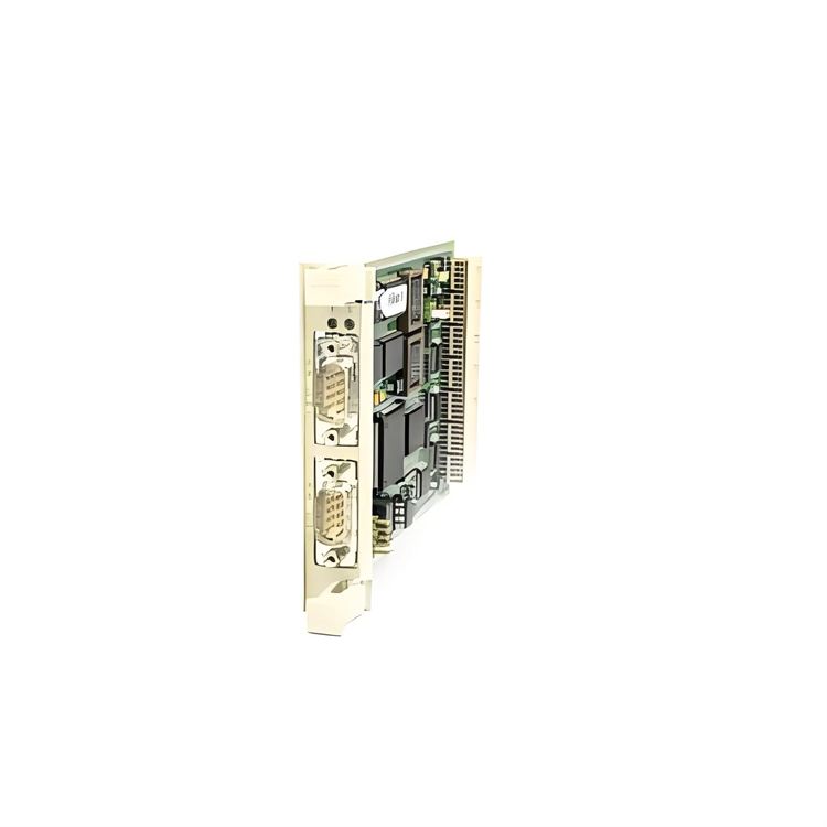
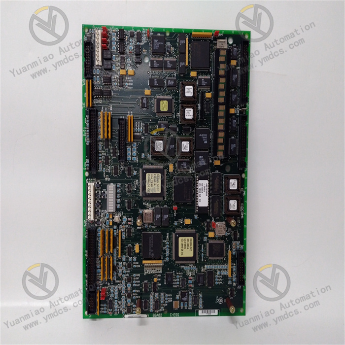
GE IS230TBAIH2C
I. Overview
The GE IS230TBAIH2C is a high-performance control interface module and a core interface component of the Mark VIe series control system. It is custom-developed for high-reliability control scenarios of large rotating machinery such as gas turbines and steam turbines. Adopting a highly integrated and stable industrial-grade hardware architecture, this module integrates multi-channel signal acquisition, high-speed data transmission, precise control signal output, and robust anti-interference design. It enables real-time and accurate monitoring of operating parameters of rotating machinery, efficient and reliable execution of control commands, and dynamic feedback of system operating status.
II. Functional Features
As a dedicated interface module for rotating machinery control scenarios, the GE IS230TBAIH2C deeply integrates GE’s years of technical accumulation in the industrial control field, with the following core functional features:
- Multi-Channel High-Precision Signal Acquisition:Equipped with 10 analog input channels, it supports the acquisition of 4-20mA DC standard current signals and K-type thermocouple temperature signals, enabling accurate capture of key operating parameters of turbines, such as rotational speed, vibration amplitude, bearing temperature, fuel pressure, and steam pressure. The analog acquisition accuracy reaches ±0.08% FS, and the sampling refresh rate is increased to 150Hz, which can quickly respond to subtle parameter fluctuations and provide millisecond-level precise data support for control decisions. Additionally, it is configured with 20 digital input channels (24V DC) for collecting discrete signals such as limit switch status, solenoid valve action feedback, and emergency stop signals. The input circuit adopts a 2500V AC photoelectric isolation design, which effectively resists strong electromagnetic interference in industrial sites and ensures the stability of signal acquisition.
- Flexible and Precise Control Signal Output:It has 7 analog output channels (4-20mA DC) with an output accuracy of ±0.15% FS and a load driving capacity of up to 550Ω. These channels can directly drive control components such as valve positioners and actuators, realizing fine adjustment of parameters like valve opening, fuel supply flow, and air intake volume. Equipped with 14 digital output channels, it adopts a relay output mode (rating: 2.5A/250V AC) and supports independent configuration as normally open or normally closed mode. It can be used in scenarios such as equipment start-stop control, sound and light alarm output, solenoid valve action control, and safety interlock triggering. The output circuit has a built-in overcurrent and short-circuit protection mechanism; when the load is abnormal or a short circuit occurs, it can quickly cut off and lock the output circuit to avoid module damage. After the fault is eliminated, the output can be restored through software reset.
- High-Speed Communication and Flexible System Integration:It adopts GE’s exclusive Genius Bus communication protocol, combined with dual-port redundant communication interfaces, with a maximum communication rate of up to 1Mbps. It supports master-slave communication mode and automatic redundant link switching, ensuring the real-time performance and reliability of data transmission. This module can be directly connected to the Mark VIe control system to achieve high-speed data interaction with the main controller and other interface modules; at the same time, it supports compatibility with general industrial protocols such as Modbus RTU and Profinet through a protocol conversion gateway, easily meeting the cross-platform integration needs of third-party PLCs and SCADA monitoring systems, and realizing centralized management, remote monitoring, and operation & maintenance of equipment operating status.
- Full-Dimension Fault Diagnosis and Redundancy Protection:Built with an enhanced self-diagnosis module, it real-time monitors the module’s power supply status, communication link integrity, signal stability of input/output channels, and working status of internal core circuits. When faults such as channel short circuit, communication interruption, abnormal power voltage, or component overheating are detected, it can trigger an alarm within 6ms, upload detailed fault codes and fault information through the communication interface, and light up the corresponding LED fault indicator, facilitating maintenance personnel to quickly locate the fault point. It supports module-level hot redundancy configuration; the main and standby modules realize real-time synchronization of collected data, control commands, and operating status through a dedicated synchronization interface. When the main module fails, the standby module can automatically switch seamlessly within 10ms, ensuring uninterrupted control processes and significantly improving the system’s fault tolerance and reliability.
- Industrial-Grade Enhanced Reliability Design:It uses components selected for a wide temperature range, with an operating temperature range of -40℃~75℃ and a storage temperature range of -55℃~85℃, which can easily adapt to extreme industrial environments such as high-temperature machine rooms and low-temperature outdoor areas. The interior of the module adopts a modular circuit layout and an independent heat dissipation cavity design; the heat sink is closely attached to power components, and combined with an intelligent temperature-controlled fan (automatically activated when the temperature ≥55℃), it can effectively control the temperature rise of core components and avoid overheating damage. The housing is made of flame-retardant aluminum alloy with an IP20 protection rating, and has excellent vibration resistance (5-500Hz, 1.2g acceleration) and impact resistance (12g, 11ms) performance. It complies with the IEC 61000-6-2/4 industrial electromagnetic compatibility standard, with a Mean Time Between Failures (MTBF) of more than 160,000 hours.
- Convenient Configuration and Operation & Maintenance Management:It supports parameter configuration, channel function configuration, control logic programming, and fault diagnosis through GE’s dedicated ToolboxST configuration software. The software has a built-in library of dedicated function blocks for rotating machinery control, such as rotational speed PID adjustment, load distribution logic, vibration threshold judgment, and temperature over-limit alarm. It adopts a drag-and-drop programming method, which greatly reduces the development difficulty and cycle of control logic. The front of the module is equipped with a 2.0-inch LCD display and 4 operation buttons, which can locally display real-time collected parameters of each channel, module operating status, and fault information, and support operations such as local parameter fine-tuning, fault reset, and channel self-test. At the same time, it supports online debugging and firmware upgrade without disconnecting the system power supply, greatly improving the efficiency of debugging and maintenance.
III. Technical Parameters
| Parameter Category | Parameter Name | Specific Parameters | Unit |
|---|---|---|---|
| Basic Parameters | Model | GE IS230TBAIH2C | - |
| Overall Dimensions (L×W×H) | 230×180×82 | mm | |
| Weight | Approximately 1.65 | kg | |
| Installation Method | Rack-mounted (compatible with GE Mark VIe standard cabinet) | - | |
| Power Supply Parameters | Power Supply Voltage | DC 24V (±10%) | V |
| Rated Power Supply Current | 3.5A | A | |
| Power Consumption | ≤80W | W | |
| Power Supply Redundancy | Supports dual-channel independent power input redundancy | - | |
| I/O Parameters | Analog Input Channels | 10 channels, 4-20mA DC/K-type thermocouple, ±0.08% FS accuracy | Channel |
| Digital Input Channels | 20 channels, 24V DC, 2500V AC photoelectric isolation | Channel | |
| Analog Output Channels | 7 channels, 4-20mA DC, ±0.15% FS accuracy, 550Ω load | Channel | |
| Digital Output Channels | 14 channels, relay output, 2.5A/250V AC | Channel | |
| Isolation Voltage | 2500V AC (mutual isolation between input/output/power) | V | |
| Sampling Refresh Rate | 150Hz (analog input), 1ms (digital input) | Hz/ms | |
| Communication & Reliability Parameters | Communication Interfaces | 2 Genius Bus channels, supporting redundancy | Channel |
| Communication Rate | 1Mbps | bps | |
| Operating Temperature Range | -40~75 | ℃ | |
| Mean Time Between Failures (MTBF) | ≥160,000 | Hour |
IV. Working Principle
Based on the closed-loop workflow of "signal acquisition - data processing - logic calculation - command output - communication interaction - fault protection", the GE IS230TBAIH2C realizes efficient collaborative control between the Mark VIe control system and the rotating machinery itself. The specific working principle is as follows:
- Multi-Type Signal Acquisition Stage:Various sensor signals from the rotating machinery (such as 4-20mA current signals from speed sensors, K-type thermocouple signals for bearing temperature, and 24V DC discrete signals from limit switches) are connected to the corresponding input channels of the module. The analog input channels have built-in high-precision signal conditioning circuits, which filter, amplify, and linearize the collected signals; for K-type thermocouple signals, cold-junction compensation is also performed to effectively eliminate errors caused by on-site electromagnetic interference and temperature drift. Then, a 16-bit high-precision A/D converter converts the analog signals into digital signals; the digital input channels realize signal isolation through a photoelectric isolation circuit, and then the signals are shaped by a Schmitt trigger to ensure the integrity and reliability of discrete signals.
- The collected digital signals are transmitted to the core control unit (adopting a GE-customized 32-bit industrial MCU) through the internal high-speed data bus, completing the signal acquisition process. The analog acquisition delay is ≤6ms, and the digital response time is ≤1ms, ensuring the real-time performance of data acquisition.
- Data Processing and Logic Calculation Stage:The core MCU first performs calibration, scaling conversion, and other processing on the collected digital signals, converting the raw data into intuitive actual physical quantities (for example, converting 4-20mA current signals into rotational speed values of 0-3000rpm, and converting K-type thermocouple signals into temperature values of 0-400℃). Then, according to the control logic issued by the Mark VIe main controller (such as rotational speed PID adjustment algorithm, load distribution strategy, safety interlock logic, etc.), the MCU performs precise calculations combined with real-time collected operating parameters to generate corresponding control commands. For example, when it is detected that the turbine speed is lower than the set value, an analog command to increase the opening of the fuel supply valve is output after calculation; when the bearing temperature exceeds the threshold, a digital command to trigger an alarm and a load reduction control signal are generated.
- At the same time, the MCU continuously calls the self-diagnosis program to real-time monitor parameters such as the module’s power supply voltage, communication link signal strength, input/output channel current/voltage, and core component temperature, and compares them with preset thresholds. If an abnormal situation is detected, it immediately generates fault information and marks the fault type.
- Control Command Output Stage:After the control commands generated by the MCU are transmitted to the output channel circuit, the analog control commands are converted into 4-20mA standard current signals by a 16-bit D/A converter, and then amplified by a power drive circuit before being output to control components such as valve positioners and actuators, realizing precise adjustment of controlled parameters; the digital control commands drive the relay to close or open through a relay drive chip, outputting switch signals to controlled equipment (such as alarm lights, fuel pumps, solenoid valves, etc.) to realize start-stop control or state switching of the equipment.
- The built-in overcurrent and short-circuit protection circuit in the output channel real-time monitors the output status. When it is detected that the output current exceeds 2.5A or a short circuit occurs, it quickly cuts off and locks the output circuit, and at the same time uploads the fault information to the core MCU; after the fault is eliminated, a reset operation through the configuration software or local buttons is required to restore the output function.
- Communication Interaction and Data Synchronization Stage:The module establishes a redundant communication link with the Mark VIe main controller through the Genius Bus communication interface, and uploads the collected real-time operating parameters, the module’s own operating status, and fault information according to the preset communication cycle (configurable within the range of 1-10ms). At the same time, it receives the control logic, parameter setting values, control commands, and other information issued by the main controller, realizing bidirectional and efficient data interaction.
- In the redundancy configuration scenario, the main and standby modules realize real-time synchronization of collected data, control commands, and operating status through a dedicated synchronization interface. The main module sends a heartbeat signal to the standby module every 1ms, and the standby module real-time monitors the operating status of the main module to ensure data consistency between the main and standby modules.
- Redundancy Switching and Fault Handling Stage:When the main module fails (such as communication interruption, power failure, core circuit abnormality, component overheating, etc.), the standby module detects the loss of the heartbeat signal or fault information within 10ms, and immediately switches to the working state automatically, fully taking over the control output and communication tasks of the main module to ensure uninterrupted control processes and minimize the impact of the fault on equipment operation. The faulty module automatically enters the fault isolation state to avoid secondary interference to the system.
- While the fault information is uploaded to the control system through the communication interface, the local LCD display of the module will real-time display the fault code and fault cause, and the corresponding LED fault indicator will flash to alarm. Maintenance personnel can query the fault information remotely through the configuration software or on-site to quickly carry out fault troubleshooting and maintenance work.
V. Common Faults and Troubleshooting Methods
| Fault Phenomenon | Fault Code | Possible Causes | Troubleshooting Methods | Precautions |
|---|---|---|---|---|
| No response after module power-on, power indicator not on | None | 1. Power supply not connected or terminal loose; 2. Power voltage out of DC 24V±10% range; 3. Both dual-channel power supplies faulty; 4. Internal power module of the module burned out; 5. Power circuit fuse blown | 1. Check the power wiring, re-plug and fasten the terminals; 2. Measure the power voltage with a multimeter to ensure it is within the range of 21.6-26.4V DC; 3. Switch to the standby power supply and observe whether the module starts normally; 4. If there is still no response after replacing the power supply, contact GE after-sales technicians to inspect the internal power module; 5. Remove the module housing and replace the fuse with the same specification (12A/250V AC) | Before replacing the fuse, thoroughly check the short-circuit fault point; use special tools to remove the module housing to avoid damaging internal circuits; dual-channel power supplies must be connected to independent power circuits to ensure redundancy protection effect |
| Large deviation or frequent fluctuation of analog input data | ERR-01 (Analog Input Fault) | 1. Loose or poor contact of sensor-module wiring; 2. Abnormal output signal caused by sensor failure; 3. Input cable not using shielded wire or poor grounding of shield layer; 4. Faulty signal conditioning circuit; 5. Lost module calibration parameters | 1. Check the wiring between the sensor and the module, and re-fasten the terminals; 2. Connect a standard signal source (such as a 4-20mA signal generator, standard temperature source) to the channel to verify whether the data is normal; if abnormal, replace the sensor; 3. Replace with shielded twisted-pair wire and ensure single-point grounding of the shield layer; 4. Contact GE after-sales to inspect the signal conditioning circuit and replace faulty components; 5. Re-calibrate the corresponding analog input channel through the ToolboxST configuration software | A standard signal source with an accuracy of ≥0.02% is required for calibration; multi-point grounding of the shield layer is prohibited to prevent the formation of a ground loop and introduction of interference; K-type thermocouple calibration must be performed with a standard temperature furnace |
| Communication interruption, unable to interact with the Mark VIe main controller | ERR-03 (Communication Fault) | 1. Damaged, aging communication cable or reversed A/B wires; 2. Mismatched communication parameters (address, baud rate) between the module and the main controller; 3. Faulty communication port of the main controller; 4. Damaged module communication interface; 5. Both redundant communication links faulty | 1. Replace with a dedicated shielded communication cable for Genius Bus and verify whether the wiring sequence is correct; 2. Check the communication parameters through the configuration software to ensure consistency with the main controller parameters; 3. Switch to the standby communication port of the main controller and test whether communication is restored; 4. Replace the module with a standby communication interface; if the fault persists, contact GE after-sales for maintenance; 5. Check the redundant communication links and repair the faulty links | The module must be restarted for modified communication parameters to take effect; a 120Ω matching resistor must be connected to the end of the Genius Bus; communication cables must be routed away from high-voltage cables to avoid electromagnetic interference |