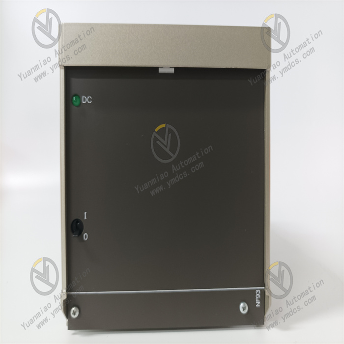
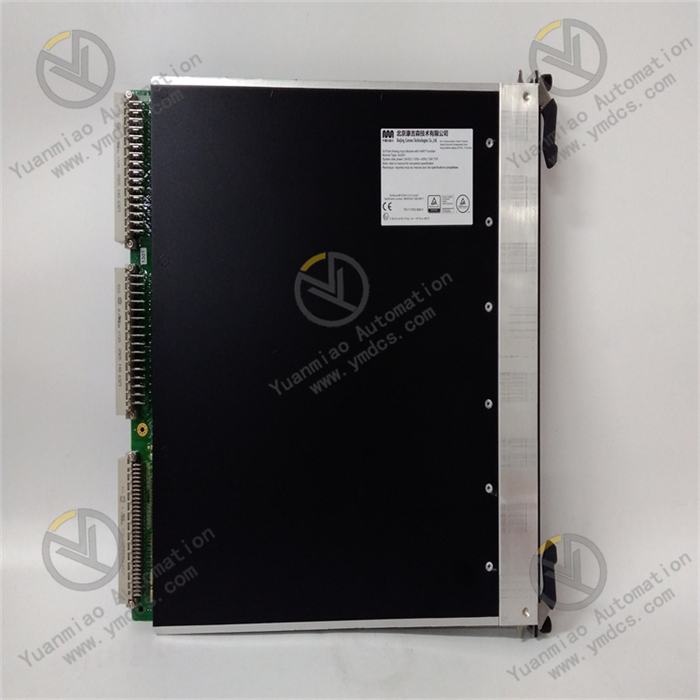
Description
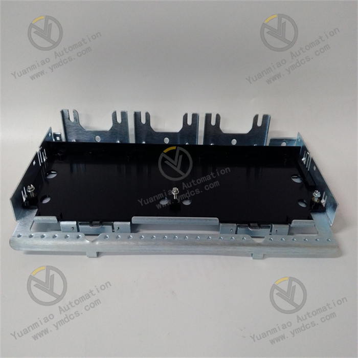
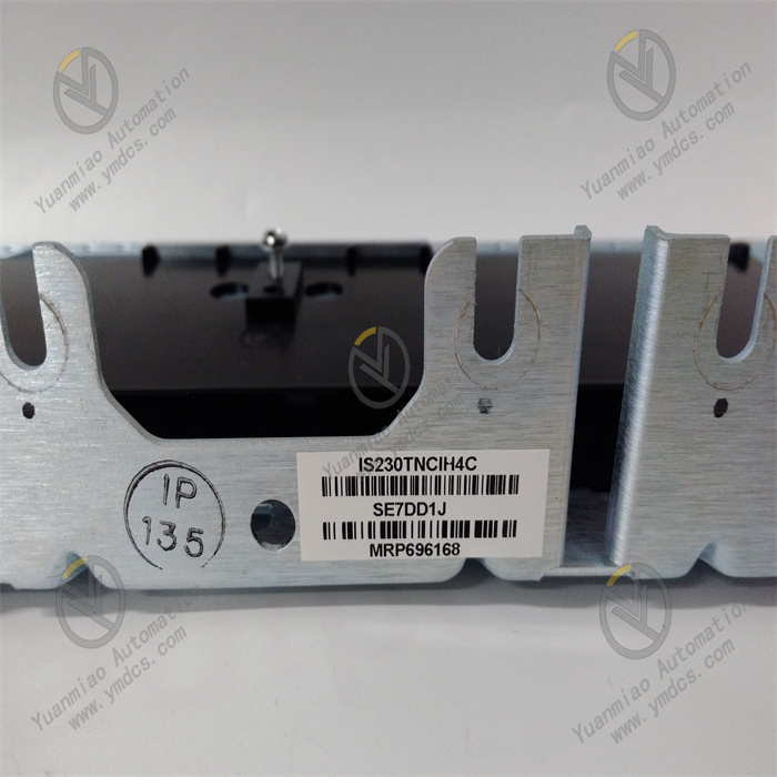
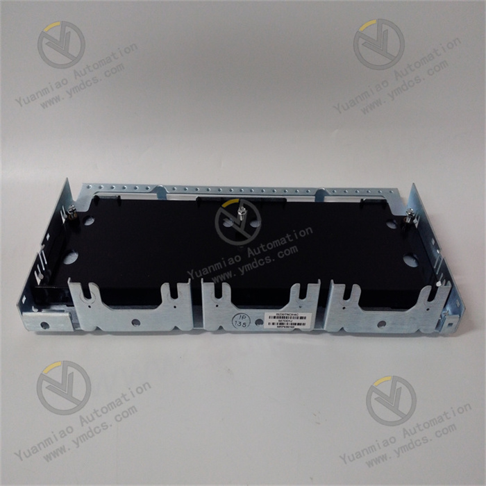
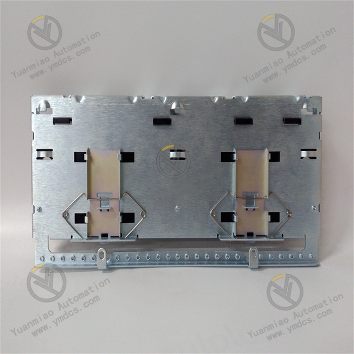
GE IS230TNCIH4C
I. Overview
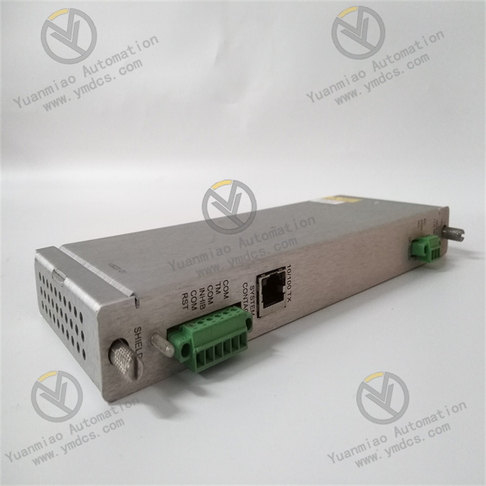
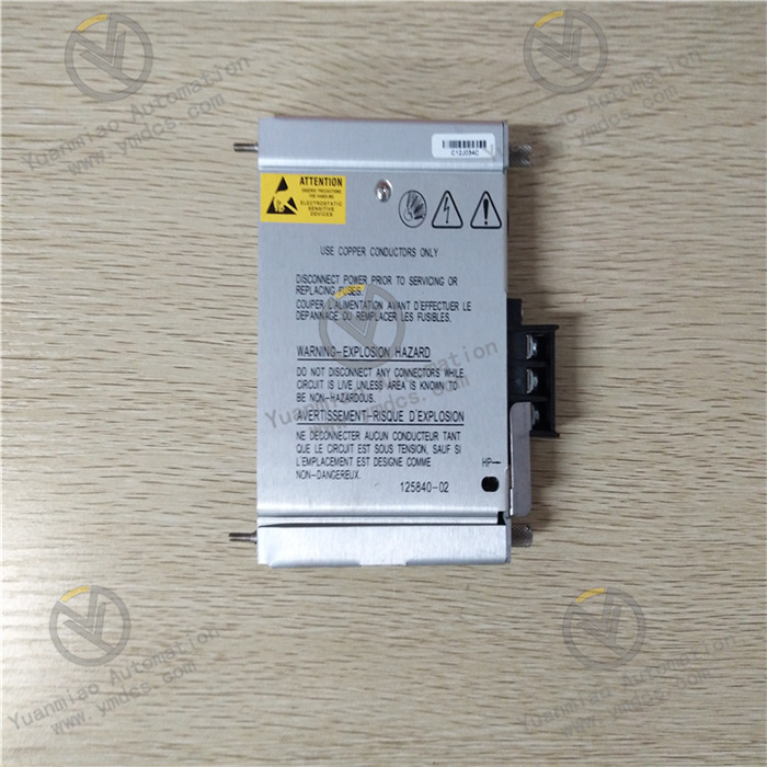
The GE IS230TNCIH4C is a control interface module, serving as a core interface component of the Mark VIe series control system. It is specifically designed for the control scenarios of large rotating machinery such as gas turbines and steam turbines. Adopting a highly reliable industrial-grade hardware architecture, this module features multi-channel signal acquisition, high-speed data transmission, precise control signal output, and strong anti-interference capability. It enables real-time monitoring of turbine operating parameters and efficient execution of control commands.
As a key bridge between the Mark VIe control system and the turbine's built-in sensors/actuators, it can seamlessly integrate with GE's PLCs, HMIs, and monitoring platforms. It provides core interface support for turbine start-stop control, load adjustment, and fault early warning, and is widely used in the control systems of large power equipment in fields such as electric power, petrochemicals, and metallurgy to ensure the safe, stable, and efficient operation of equipment.
II. Functional Features
As a dedicated interface module for turbine control scenarios, the GE IS230TNCIH4C integrates GE's core technologies in the industrial control field. Its core functional features are as follows:
- Multi-channel High-precision Signal Acquisition:It supports 8 analog input channels (4-20mA DC standard signal) for accurately collecting key operating parameters of the turbine, such as rotational speed, vibration, temperature, pressure, and oil level. The analog acquisition accuracy reaches ±0.1% FS, and the sampling refresh rate is as high as 100Hz, enabling rapid capture of parameter fluctuations to provide accurate data support for control decisions. Additionally, it is equipped with 16 digital input channels (24V DC) for collecting discrete signals such as limit switch signals and status feedback. The input signals feature photoelectric isolation with an isolation voltage of 2500V AC, effectively resisting on-site interference.
- Flexible Control Signal Output:It is provided with 6 analog output channels (4-20mA DC) that can output control commands to turbine actuators (e.g., adjusting valve opening, controlling oil supply pressure). The output accuracy is ±0.2% FS, and the output load capacity is up to 500Ω, compatible with various industrial-grade actuators. It also has 12 digital output channels (relay output, 2A/250V AC) for controlling equipment start-stop, fault alarm, and solenoid valve action. The output channels support independent configuration and can be set to normally open or normally closed mode as needed.
- High-speed Data Transmission and System Integration:It adopts GE's proprietary Genius Bus communication protocol and is equipped with dual-port communication interfaces, supporting a redundant communication architecture with a communication rate of 1Mbps to ensure real-time and reliable data transmission. It can be directly connected to the Mark VIe control system to achieve data interaction with controllers and monitoring modules within the system. Meanwhile, it supports conversion to general industrial protocols such as Modbus and Profinet via a gateway module, adapting to the integration needs of third-party PLCs and SCADA systems to realize cross-platform data sharing and centralized management.
- Comprehensive Fault Diagnosis and Redundant Protection:A built-in complete self-diagnosis module enables real-time monitoring of the module's own power supply status, communication status, and input/output channel faults. When an abnormality is detected, it immediately uploads fault codes (e.g., channel short circuit, communication interruption, power supply abnormality) via the communication interface and triggers a local LED fault indicator alarm. It supports module-level redundant configuration and can form a redundant backup with modules of the same model. When the main module fails, the standby module automatically switches within 10ms to ensure uninterrupted control processes and improve system reliability.
- Industrial-grade High-reliability Design:It uses wide-temperature-range components, with an operating temperature range of -40℃~70℃ and a storage temperature range of -55℃~85℃, adaptable to extreme industrial environments such as high and low temperatures. The module adopts a modular circuit design and an independent heat dissipation structure inside, with heat sinks arranged in isolation from the circuit to effectively reduce the temperature rise of power devices. The housing is made of flame-retardant aluminum alloy with an IP20 protection rating, featuring vibration resistance (5-500Hz, 1g acceleration) and impact resistance (10g, 11ms) capabilities. It complies with the IEC 61000-6-2 industrial electromagnetic compatibility standard, with a Mean Time Between Failures (MTBF) of more than 150,000 hours.
- Convenient Configuration and Operation & Maintenance:It supports parameter configuration, channel configuration, and fault diagnosis operations via GE's dedicated configuration software (e.g., ToolboxST). The software has built-in dedicated function blocks for turbine control (e.g., rotational speed adjustment, load control, fault logic judgment), enabling quick establishment of control logic. The module is equipped with clear LED status indicators that display the power supply, communication, and operating status of each channel in real time, facilitating on-site operation and maintenance personnel to intuitively judge the equipment status. It supports online debugging and parameter modification without disconnecting the system power supply, improving debugging and maintenance efficiency.
III. Technical Parameters
| Parameter Category | Parameter Name | Specific Parameters | Unit |
|---|---|---|---|
| Basic Parameters | Model | GE IS230TNCIH4C | - |
| Overall Dimensions (L×W×H) | 220×180×80 | mm | |
| Weight | Approximately 1.5 | kg | |
| Installation Method | Rack-mounted (compatible with GE Mark VIe standard cabinet) | - | |
| Power Supply Parameters | Power Supply Voltage | DC 24V (±10%) | V |
| Rated Power Supply Current | 3A | A | |
| Power Consumption | ≤70W | W | |
| Power Supply Redundancy | Supports dual-channel power input redundancy | - | |
| I/O Parameters | Analog Input Channels | 8 channels, 4-20mA DC, ±0.1% FS accuracy | Channel |
| Digital Input Channels | 16 channels, 24V DC, photoelectric isolation | Channel | |
| Analog Output Channels | 6 channels, 4-20mA DC, ±0.2% FS accuracy, 500Ω load | Channel | |
| Digital Output Channels | 12 channels, relay output, 2A/250V AC | Channel | |
| Isolation Voltage | 2500V AC (between input/output and power supply) | V | |
| Sampling Refresh Rate | 100Hz (analog input) | Hz | |
| Communication & Reliability Parameters | Communication Interfaces | 2 Genius Bus interfaces, supporting redundancy | Channel |
| Communication Rate | 1Mbps | bps | |
| Operating Temperature Range | -40~70 | ℃ | |
| Mean Time Between Failures (MTBF) | ≥150,000 | Hour |
IV. Working Principle
Based on the core workflow of "signal acquisition - data processing - command output - communication interaction - fault diagnosis", the GE IS230TNCIH4C realizes efficient linkage between the Mark VIe control system and the turbine's built-in equipment. The specific working principle is as follows:
- Multi-type Signal Acquisition Stage:Sensor signals from the turbine (e.g., 4-20mA analog signals from speed sensors, 24V DC digital signals from limit switches) are connected to the corresponding input channels of the module. The analog input channels have a built-in signal conditioning circuit that filters, amplifies, and linearizes the collected signals to eliminate on-site electromagnetic interference, and then converts the analog signals into digital signals via a 16-bit A/D converter. The digital input channels isolate external signals from the internal circuit through a photoelectric isolation circuit to prevent interference from entering, and simultaneously shape the signals to ensure signal integrity.
- The collected digital signals are transmitted to the module's core microprocessor (adopting GE's proprietary industrial-grade MCU) via the internal data bus, completing the signal acquisition process. The analog acquisition refresh rate reaches 100Hz, and the digital acquisition response time is ≤1ms.
- Data Processing and Control Logic Calculation Stage:The core microprocessor calibrates and scales the collected digital signals, converting the raw data into actual physical quantities (e.g., converting 4-20mA signals into rotational speed values of 0-3000rpm). Subsequently, based on the control logic issued by the Mark VIe control system (e.g., speed adjustment logic, load control logic) and combined with the collected real-time parameters, the microprocessor performs calculations to generate control commands. For example, when the turbine speed is lower than the set value, a control command to increase the valve opening is generated after calculation; when excessive vibration is detected, an alarm and load reduction command are generated.
- At the same time, the microprocessor calls the self-diagnosis program to monitor parameters such as the module's power supply status, communication status, and input/output channel voltage/current in real time, judges the module's operating status, and generates fault information if an abnormality is detected.
- Control Command Output Stage:The control commands generated by the microprocessor are transmitted to the output channel circuit: the analog output commands are converted into 4-20mA standard analog signals via a D/A converter, amplified by the output drive circuit, and then transmitted to actuators (e.g., valve positioners) to adjust the actuator action. The digital output commands control the relay to pull in or disconnect via the relay drive circuit, outputting switch signals to the controlled equipment (e.g., alarm lights, solenoid valves).
- The output channels are equipped with overcurrent and short-circuit protection functions. When the output current exceeds the rated value or a short circuit occurs, the output is quickly cut off to protect the module and the controlled equipment from damage; after the fault is eliminated, automatic output recovery is supported.
- Communication Interaction Stage:The module establishes a redundant communication connection with the main controller of the Mark VIe control system via the Genius Bus communication interface, uploading collected real-time parameters, module operating status, and fault information to the main controller. At the same time, it receives control logic, parameter setting values, and control commands issued by the main controller to realize bidirectional data interaction. The communication rate reaches 1Mbps, ensuring the real-time performance of data transmission to meet the real-time control needs of the turbine.
- When integration with third-party systems is required, the Genius Bus protocol is converted into general protocols such as Modbus and Profinet via a gateway module to realize data sharing with third-party PLCs and SCADA systems, supporting remote monitoring and control.
- Redundancy Switching and Fault Handling Stage:In redundant configuration scenarios, the main and standby modules synchronize data (e.g., collected parameters, control commands, operating status) in real time via a dedicated redundancy interface. The main module sends a heartbeat signal to the standby module in real time, and the standby module monitors the status of the main module. When the main module fails (e.g., communication interruption, power failure), the standby module detects the abnormality and automatically switches to the main module within 10ms, taking over the control task to ensure uninterrupted control processes and improve system reliability.
- When a fault is detected, the module issues a local alarm via LED fault indicators (e.g., communication fault light, power fault light, channel fault light) and simultaneously uploads the fault code and fault information to the control system via the communication interface, facilitating timely troubleshooting by operation and maintenance personnel.
V. Common Faults and Troubleshooting Methods
| Fault Phenomenon | Fault Code | Possible Causes | Troubleshooting Methods | Precautions |
|---|---|---|---|---|
| No response after module power-on, power indicator not on | None | 1. Power supply not connected or wiring loose; 2. Abnormal power supply voltage (<21.6V or >26.4V DC); 3. Both dual-channel power supplies faulty; 4. Internal power module damaged; 5. Power fuse burned | 1. Check the power supply wiring, re-plug and fasten the terminals; 2. Use a multimeter to test the power supply voltage to ensure it is within the range of 24V±10%; 3. Switch to the standby power supply and check if it recovers; 4. If there is still no response after replacing the power supply, contact GE after-sales to inspect the power module; 5. Remove the module housing and replace the fuse with the same specification (10A/250V AC) | Before replacing the fuse, check for short-circuit causes; use special tools to remove the housing to avoid damaging the internal circuit; dual-channel power supplies must be connected to different power circuits to ensure redundancy effect |
| Large fluctuation of analog input data, substandard accuracy | ERR-01 (Input Channel Fault) | 1. Loose or poor contact of sensor wiring; 2. Faulty sensor with unstable output signal; 3. Input channel affected by electromagnetic interference; 4. Faulty signal conditioning circuit; 5. Lost module calibration parameters | 1. Check the wiring between the sensor and the module, re-fasten the terminals; 2. Replace the sensor for testing and replace it if the fault is confirmed; 3. Check the grounding of the input cable shield, add a magnetic ring for anti-interference, and keep it away from high-interference equipment; 4. Contact GE after-sales to inspect the signal conditioning circuit and replace faulty components; 5. Re-calibrate the analog input channel parameters via the configuration software | A standard signal source (e.g., 4-20mA signal generator) is required for parameter calibration; shielded twisted-pair cables must be used for input cables, with single-point grounding of the shield layer |
| Communication interruption, unable to interact with Mark VIe controller | ERR-03 (Communication Fault) | 1. Damaged communication cable or incorrect wiring; 2. Mismatched communication parameters (address, baud rate); 3. Faulty communication port of the main controller; 4. Damaged module communication interface; 5. Both redundant communication links faulty | 1. Replace the dedicated Genius Bus communication cable and verify the wiring; 2. Check the communication parameters via the configuration software to ensure consistency with the main controller; 3. Switch to the standby communication port of the main controller; 4. Replace the module with the standby communication interface; if the fault persists, contact after-sales for repair; 5. Check the redundant communication links and repair the faulty links | The module must be restarted for modified communication parameters to take effect; redundant communication cables must be routed separately to avoid simultaneous faults; a matching resistor must be connected to the end of the Genius Bus |
| No analog output signal, actuator not working | ERR-02 (Output Channel Fault) | 1. Loose or broken output wiring; 2. Faulty actuator or excessive load; 3. Protection triggered by output channel short circuit; 4. Faulty D/A converter; 5. Damaged output drive circuit | 1. Check the output wiring and re-fasten the terminals; 2. Disconnect the output wiring, use a multimeter to test the module's output signal; if normal, repair the actuator; 3. Locate and repair the short-circuit point, then restart the module to restore output; 4. Contact GE after-sales to inspect the D/A converter; 5. Replace components of the output drive circuit (to be operated by professional engineers) | The actuator must be disconnected when testing the output signal to avoid load impact; output channel short circuits may burn the drive circuit, requiring timely troubleshooting; the actuator load must not exceed 500Ω |
| Redundancy switching failure, standby module not taking over after main module failure | ERR-05 (Redundancy Fault) | 1. Unconnected or loose redundant communication cable; 2. Incorrect redundancy parameter configuration; 3. Standby module not powered on or faulty; 4. Faulty redundancy control circuit; 5. Inconsistent firmware versions of main and standby modules | 1. Check the redundant communication cable and re-fasten the terminals; 2. Verify the redundancy parameters via the configuration software to ensure correct address and role configuration of the main and standby modules; 3. Check the power supply and status of the standby module to eliminate faults of the standby module; 4. Contact GE after-sales to inspect the redundancy control circuit; 5. Upgrade the firmware of the main and standby modules to the same version | Redundancy parameters must be configured in strict accordance with GE manuals; firmware upgrade must be performed when the system is shut down to avoid system faults caused by upgrade failures; the main and standby modules must be of the same model and version |


