Description
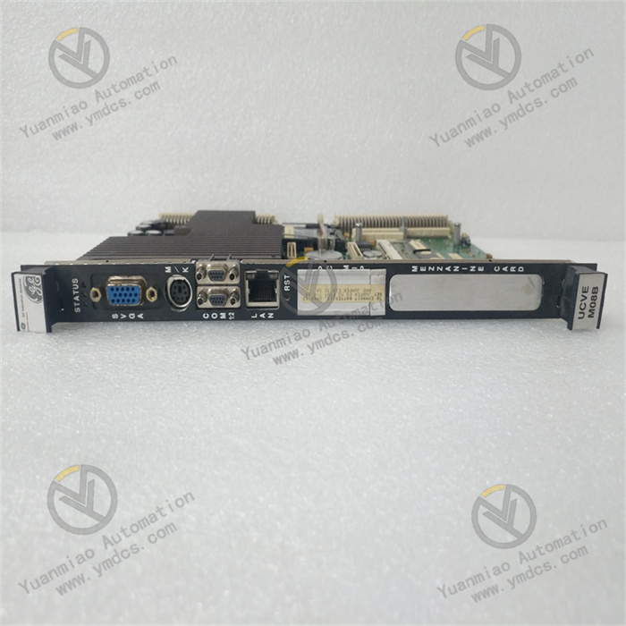
GE IS215UCVEM08B
I. Product Overview
IS215UCVEM08B is a high-precision analog input/output (I/O) module developed for the Mark VIe series gas turbine/steam turbine control system, and it belongs to the core I/O unit family of the Mark VIe system. As a key interface between the system and on-site equipment, this module mainly realizes the collection of analog signals in industrial fields (such as sensor signals for temperature, pressure, flow rate, liquid level, etc.) and the output of analog control signals (such as control signals for actuators and control valves). It is widely used in fields with extremely high requirements for control accuracy and reliability, such as electric power, petrochemical, metallurgy, aerospace, etc., and is a core component of the Mark VIe system for achieving accurate monitoring of unit operation status and closed-loop control.
Based on GE's advanced industrial-grade I/O processing architecture, this module adopts a 32-bit dedicated microprocessor and high-precision signal conditioning chips. It features high signal acquisition accuracy, good output stability, strong anti-interference capability, hot-swap support, and comprehensive diagnostic functions. It has passed the IEC 61508 functional safety certification (SIL 3 level), IEC 61000-6-4 electromagnetic compatibility certification, and UL 508 industrial safety certification. It can operate stably in harsh industrial environments with a wide temperature range of -40℃ to 70℃, high humidity, high dust, and strong electromagnetic interference. It is fully compatible with the distributed I/O topology of the Mark VIe system and meets the high reliability and high real-time requirements of large-scale units for control system I/O interfaces.
II. Functional Features
- High-Precision Analog Signal Acquisition and Output: The module integrates 8 configurable analog input channels and 4 analog output channels. The input channels support the acquisition of 4~20mA current signals, 0~10V voltage signals, thermocouple (types such as K, J, T, E) signals, and thermal resistance (Pt100, Cu50) signals. The signal type of the channels can be flexibly configured through software without hardware jumpers. The input acquisition accuracy reaches ±0.02% FS, the temperature acquisition accuracy of thermocouples is ±0.1℃, the temperature acquisition accuracy of thermal resistances is ±0.05℃, and the sampling frequency is 1kHz per channel, which can accurately capture subtle changes in on-site signals. The output channels support 4~20mA current output or 0~10V voltage output, with an output accuracy of ±0.05% FS, a load regulation rate of ≤±0.03%, and an output response time of ≤10ms. They can stably drive various industrial actuators and regulating equipment to ensure the accurate execution of control commands.
- Strong Anti-Interference and Signal Conditioning Capability: Each input/output channel adopts an independent signal conditioning circuit and photoelectric isolation design, with an isolation voltage of 2500V AC (between input and system, output and system, and between channels), which effectively suppresses common-mode interference and differential-mode interference. The input channels have a built-in programmable gain amplifier (PGA) and low-pass filter, which can automatically adjust the gain (1~1000 times adjustable) according to the signal amplitude and filter out high-frequency noise (cut-off frequency 10Hz~1kHz adjustable). The thermocouple channels integrate a cold-junction compensation circuit with a compensation accuracy of ±0.1℃, which solves the impact of ambient temperature changes on measurement accuracy. The output channels adopt a constant current/constant voltage dual-mode drive circuit, with short-circuit protection and overload protection functions. When the output is short-circuited, it can automatically limit the current to 25mA, and automatically recover after the fault is eliminated, avoiding damage to the module and load equipment.
- Comprehensive Self-Diagnosis and Fault Monitoring: The module has built-in dual-level diagnostic functions (channel-level and module-level). A dedicated microprocessor monitors the signal amplitude of each channel, line connection status (open circuit, short circuit), sensor faults (such as thermocouple disconnection, thermal resistance short circuit), working status of signal conditioning chips, and module power supply status in real time. The diagnostic information includes the fault channel number, fault type (such as over-range, open circuit, short circuit), fault timestamp, and signal waveform data before and after the fault. It can be displayed in real time through the Control ST configuration software of the Mark VIe system and uploaded to the controller and background monitoring system via the communication bus. The front panel of the module is equipped with LED status indicators, with independent "normal/fault" indicators for each channel. The module as a whole is equipped with "power supply", "communication", and "operation" indicators, which can quickly locate the fault location on site.
- Hot-Swap and Redundancy Backup Support: The module adopts GE's patented hot-swap mechanical structure and circuit design, supporting plug-in replacement of the module without shutting down the Mark VIe system. The plug-in process does not affect the normal operation of other channels. After replacement, the module automatically completes parameter configuration and channel calibration without reconfiguration, greatly shortening the maintenance downtime. It supports module-level redundancy backup and can form a 1+1 redundancy configuration with modules of the same model. The redundant module synchronizes the configuration parameters and operation status of the main module in real time. When the main module fails, the redundant module can switch to the working state without disturbance within ≤5ms, ensuring the continuity of I/O signal acquisition and output and improving the overall reliability of the system.
- Flexible System Integration and Communication: The module adopts the standard VersaWave communication interface of the Mark VIe system, supporting high-speed communication with the system controller (such as IC695CRU320) via optical fiber or copper cable. The communication rate reaches 1Gbps, and the data transmission delay is ≤1ms, meeting the high real-time requirements of real-time control for I/O data transmission. It supports online parameter configuration and calibration. Through the Control ST software, the channel signal type, sampling frequency, filter parameters, alarm threshold, etc., can be set remotely. The configured parameters take effect immediately without restarting the module. The module supports connection with the GE Predix industrial cloud platform, and can upload I/O acquisition data and diagnostic information to the cloud to realize remote monitoring, fault early warning, and predictive maintenance.
- High Reliability and Long-Life Design: It adopts a fanless natural heat dissipation design. The module shell is made of high-strength aluminum alloy with dense heat dissipation fins. Combined with the optimized internal circuit layout, it ensures the module operates stably within a wide temperature range of -40℃ to 70℃. The core components are all industrial-grade long-life products, such as high-precision AD/DA conversion chips (service life ≥100,000 hours), imported tantalum capacitors (service life ≥80,000 hours @85℃), and gold-plated connectors (plug-in times ≥1,000 times). Combined with strict environmental stress screening (ESS) tests, the mean time between failures (MTBF) of the module is ≥200,000 hours, meeting the long-term continuous operation requirements of large-scale units.
III. Technical Parameters
| Parameter Category | Parameter Name | Specific Parameters | Unit |
|---|---|---|---|
| Basic Parameters | Model Number | IS215UCVEM08B | - |
| Product Type | Analog I/O Module for GE Mark VIe System | - | |
| Overall Dimensions (L×W×H) | 160×120×80 | mm | |
| Weight | Approximately 1.2 | kg | |
| Installation Method | Mounting on Mark VIe Standard I/O Rack (Compatible with IC695CHS392 Rack) | - | |
| Power Supply Parameters | Supply Voltage | DC 24V±20%, supporting dual-channel redundant input | V DC |
| Rated Supply Current | 1.5A (at full load operation) | A | |
| Power Consumption | ≤36W | W | |
| Power Supply Isolation | 2500V AC, between input and system | V AC | |
| Analog Input Parameters | Number of Input Channels | 8 channels, independently configurable | Channel |
| Supported Signal Types | 4~20mA (current), 0~10V (voltage), thermocouple (K/J/T/E/R/S/B/N), thermal resistance (Pt100/Cu50) | - | |
| Acquisition Accuracy | Current/voltage signals: ±0.02% FS; Thermocouple: ±0.1℃; Thermal resistance: ±0.05℃ | -/℃ | |
| Sampling Frequency | 1kHz per channel, software adjustable (10Hz~1kHz) | Hz | |
| Input Impedance | Current signal: ≤100Ω; Voltage signal: ≥10MΩ; Thermal resistance: ≤1Ω | Ω/MΩ | |
| Cold-Junction Compensation Accuracy | ±0.1℃ (for thermocouple channels) | ℃ | |
| Filtering Method | Low-pass filter, cut-off frequency 10Hz~1kHz adjustable | Hz | |
| Channel Isolation | 2500V AC, between channels and between channel and system | V AC | |
| Analog Output Parameters | Number of Output Channels | 4 channels, independently configurable | Channel |
| Supported Signal Types | 4~20mA (current), 0~10V (voltage), software switchable | - | |
| Output Accuracy | ±0.05% FS | - | |
| Load Capacity | Current output: ≤500Ω; Voltage output: ≥1kΩ | Ω | |
| Load Regulation Rate | ≤±0.03% | - | |
| Response Time | ≤10ms (0~100% output range) | ms | |
| Communication & Diagnosis Parameters | Communication Interface | GE VersaWave Interface (Optical Fiber/Copper Cable) | - |
| Communication Rate | 1Gbps | Gbps | |
| Data Transmission Delay | ≤1ms | ms | |
| Diagnostic Functions | Channel open/short circuit detection, over-range detection, sensor fault diagnosis, module power fault diagnosis, communication fault diagnosis | - | |
| Fault Record Capacity | 1000 fault records (with timestamp) | Record | |
| Environmental & Reliability Parameters | Operating Temperature Range | -40~70℃ | ℃ |
| Storage Temperature Range | -55~85℃ | ℃ | |
| Relative Humidity | 5%~95% (no condensation, at 40℃) | % | |
| Protection Level | IP20 (when mounted on rack) | - | |
| Mean Time Between Failures (MTBF) | ≥200,000 hours | Hour |
IV. Working Principle
The working principle of the IS215UCVEM08B analog I/O module revolves around the core chain of "signal acquisition - conditioning and conversion - data processing - communication transmission - output drive - diagnostic protection". Combined with high-precision signal processing technology and high-speed communication mechanism, it realizes the accurate acquisition of on-site signals and the reliable output of control commands. The specific process is as follows:
- Redundant Power Supply and System Initialization:The module is connected to a dual-channel DC 24V redundant power supply. After rectification, filtering, and voltage stabilization by the built-in power management module, it outputs stable DC voltages of +5V, +12V, and -12V to power the microprocessor module, signal conditioning module, AD/DA conversion module, and communication module respectively. The power management module monitors the voltage and current status of the two power supply channels in real time, and realizes undisturbed switching through the redundant switching circuit. When one power supply channel fails, the other channel immediately takes over the full power supply load, with a switching time of ≤1ms, and triggers a power supply fault alarm at the same time. After the module is powered on, it automatically executes the initialization program. The microprocessor performs a self-test on the memory, AD/DA chips, communication interface, and diagnostic circuit. After passing the self-test, it loads the user configuration parameters (channel type, sampling frequency, filter parameters, etc.). After the initialization is completed, the communication interface establishes a connection with the controller, and the module enters the ready state; if the self-test fails, the fault indicator flashes red and records the fault code.
- Analog Input Acquisition and Conditioning:The 8 analog input channels process different types of signals according to the configuration parameters: ① Current/voltage signals: After the signals are connected to the channels through twisted-shielded wires, they first pass through a surge suppression circuit (suppressing ±2kV surges) and an overcurrent protection circuit (current limiting ≤30mA), and then are sent to the programmable gain amplifier (PGA). The gain is automatically adjusted (1~1000 times adjustable) according to the signal amplitude to amplify the signal to the optimal input range of the AD conversion chip; the amplified signal is filtered by a low-pass filter to remove high-frequency noise, resulting in a stable analog signal. ② Thermocouple signals: The signals are connected to the channels through dedicated compensation wires, and after passing through the cold-junction compensation circuit (which collects the ambient temperature through a high-precision temperature sensor for compensation), they are sent to the PGA for amplification and filtered by the filter. ③ Thermal resistance signals: They are connected to the channels using a three-wire or four-wire connection method. A constant current source circuit applies a constant current (1mA) to the thermal resistance, and the voltage signal across the thermal resistance is collected, then amplified by the PGA and filtered by the filter. The processed analog signal is sent to a 16-bit high-precision AD conversion chip to be converted into a digital signal, with a sampling frequency of 1kHz per channel and a conversion accuracy of ±0.02% FS. The digital signal is sent to the microprocessor for data processing after photoelectric isolation.
- Data Processing and Diagnostic Analysis:The microprocessor further processes the digital signal after AD conversion: ① Linearization processing: Performs nonlinear correction on thermocouple and thermal resistance signals to ensure temperature measurement accuracy; ② Filtering processing: Uses digital filtering algorithms (such as Kalman filtering) to further filter out random noise and improve signal stability; ③ Scaling conversion: Converts the collected original digital signals into engineering units (such as ℃, MPa, m³/h). At the same time, the diagnostic module monitors the status of each channel in real time: judges whether the line is open (impedance ≥10MΩ) or short-circuited (impedance ≤10Ω) by detecting the input impedance of the channel; judges whether it is over-range by comparing the collected value with the configured range; judges whether the chip is faulty by monitoring the output signal of the AD conversion chip; judges whether the power supply is normal by monitoring the power supply voltage. If a fault is detected, it immediately records the fault information (channel number, type, timestamp), triggers the fault indicator of the corresponding channel to flash, and uploads the fault data through the communication interface.
- Communication Transmission and Command Reception:The microprocessor transmits the processed acquisition data (engineering units) and diagnostic information to the Mark VIe system controller through the VersaWave communication interface, with a communication rate of 1Gbps and a data transmission delay of ≤1ms, ensuring real-time control requirements. At the same time, the module receives control commands and configuration parameters issued by the controller through the communication interface, such as analog output commands, channel parameter modification commands, and calibration commands. The control commands are sent to the microprocessor after photoelectric isolation, and the configuration parameters are stored in non-volatile flash memory, which will not be lost when the power is off. It supports online parameter modification, and the modified parameters take effect immediately without restarting the module.
- Analog Output Drive and Protection:According to the output command issued by the controller, the microprocessor sends the digital signal to a 16-bit high-precision DA conversion chip to convert it into an analog signal. According to the configuration parameters, the analog signal is converted into a 4~20mA current signal or a 0~10V voltage signal through a voltage/current conversion circuit. The output drive circuit adopts a constant current/constant voltage dual-mode design to ensure stable output signals, with a load regulation rate of ≤±0.03%. The output circuit has a built-in short-circuit protection circuit. When the output is short-circuited (current ≥25mA), it immediately enters the current-limiting mode, limiting the output current to ≤25mA, and triggers a short-circuit fault alarm at the same time; after the fault is eliminated, it automatically returns to normal output. The output signal is transmitted to the load equipment (such as actuators, control valves) through twisted-shielded wires after photoelectric isolation, realizing accurate control of on-site equipment.
- Redundancy Switching (in Redundant Configuration):When the module is configured in 1+1 redundancy mode, the main module and the redundant module synchronize the configuration parameters, acquisition data, and output commands in real time through the communication interface. The redundancy management module monitors the operation status of the main module (such as communication status, fault status, power supply status) in real time. When the main module fails (such as communication interruption, channel fault, power supply fault), the redundancy management module immediately triggers a switching signal, and the redundant module takes over the work of the main module within ≤5ms, continuing to output control signals and upload acquisition data. The output signal fluctuation during the switching process is ≤±0.5%, realizing undisturbed switching. After the faulty main module is repaired, it can be set to resume as the main module or operate as a redundant module through software.