Description
GE IS215UCVEM06A
GE IS215UCVEM06A is an industrial-grade control module launched by General Electric (GE) of the United States. It belongs to the core component lineup of the GE Speedtronic series control systems and is custom-developed for the control scenarios of large-scale power equipment such as gas turbines, steam turbines, and combined-cycle generator sets. It is widely used in core industrial fields with strict requirements for control accuracy, reliability, and real-time performance, including power generation, petrochemicals, and energy supply. Its core function is to accurately collect signals from various on-site sensors, receive commands from upper-level systems, and complete signal processing, closed-loop regulation, interlock protection, and control command output through the built-in high-performance control algorithms and logic operation units. It realizes precise control over the entire process of start-up, operation, and shutdown of power equipment, while also having comprehensive fault diagnosis and data interaction capabilities, serving as a core control unit to ensure the safe, efficient, and stable operation of large-scale power equipment.
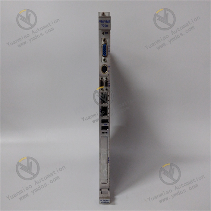
This module adopts the standard modular hardware architecture of the GE Speedtronic series, featuring excellent system compatibility and expandability. It can be directly and seamlessly integrated into GE Mark VI, Mark VIe, and Speedtronic series control systems, and can achieve high-speed data interaction with power modules, communication modules, and I/O expansion modules in the system without additional adapter modules. Adhering to strict industrial environment design standards, through multiple electromagnetic compatibility optimizations, wide-temperature adaptability enhancements, and redundancy design for key components, it can stably adapt to the harsh operating environment of industrial sites characterized by high temperature, high humidity, heavy dust, strong vibration, and strong electromagnetic interference. Relying on GE's proprietary 32-bit embedded control chip and real-time control kernel, it achieves microsecond-level response and high-precision execution of control commands, providing solid technical support for the complex control needs of large-scale power equipment.
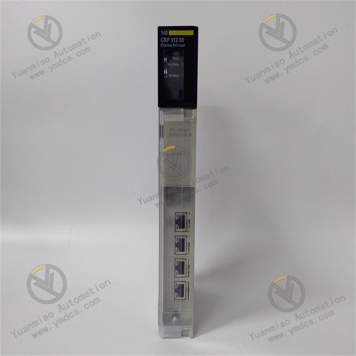
In-depth Compatibility with Speedtronic Systems & Seamless Efficient Integration: The module adopts the unified hardware interface and communication protocol of the GE Speedtronic series. It can be directly inserted into standard racks of systems such as Mark VI and Mark VIe. After power-on, it automatically completes communication handshakes and parameter synchronization with the system controller, power module, and I/O module via the high-speed backplane bus of the rack, realizing "plug-and-play" rapid integration. It supports full graphical programming with GE Proficy iFIX and CIMPLICITY configuration software, enabling intuitive completion of control logic writing, I/O channel mapping, PID parameter tuning, and alarm threshold configuration without additional development of dedicated drivers. The data interaction delay with other components in the system is ≤0.5ms, ensuring real-time synchronization of control commands and monitoring data, significantly shortening the system integration and debugging cycle, and reducing engineering costs.
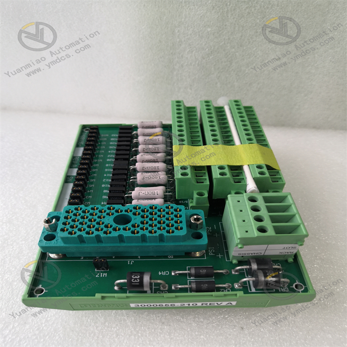
Integration of Multiple Types of High-precision I/O & Comprehensive Control Coverage: It integrates 12 analog input channels, 8 analog output channels, 16 digital input channels, 10 digital output channels, and 2 pulse input channels. It can fully connect to on-site sensor signals (such as temperature, pressure, vibration, and speed) and actuator control signals (such as solenoid valves, control valves, and contactors), realizing all-round collection of power equipment operating parameters and multi-dimensional control. The analog channels have an input accuracy of ±0.05%FS and an output accuracy of ±0.1%FS, which can accurately capture subtle changes in parameters; the digital channels support adaptive switching between dry/wet contacts, and the pulse channels can directly connect to speed sensor signals without additional signal conversion modules, improving system integration and control accuracy.
Dual-core Parallel Control Operation & Accurate Efficient Response: Equipped with a GE proprietary 32-bit dual-core embedded control processor with a main frequency of 600MHz, it adopts a dual-core parallel processing architecture. The two cores are respectively responsible for signal acquisition and calculation, and control command generation and output. The operation cycle is ≤0.5ms, which can quickly process multi-channel concurrent signals and execute complex control logic. The analog input response time is ≤0.8ms, the digital input response time is ≤0.5ms, and the output command delay is ≤1ms. It can timely capture changes in equipment operating status and output accurate control commands, and has strong adaptability to scenarios with extremely high real-time requirements such as gas turbine speed regulation and steam pressure closed-loop control. It supports complex algorithms such as PID regulation, fuzzy control, and adaptive control, which can automatically optimize control parameters according to the equipment operating conditions to meet high-precision control needs under different working conditions.
1:1 Hot Redundancy Configuration & Safe Reliable Operation: It supports 1:1 dual-module hot redundancy configuration. The main and standby modules realize real-time synchronization of input signals, operation logic, and output status through a dedicated synchronization bus, and continuously perform mutual health checks and data verification during operation. When the main module has faults such as processor failure, I/O channel abnormality, or communication interruption, the standby module can automatically switch to take over the control task without disturbance within ≤3ms. During the switching process, control commands are not interrupted and parameters are not fluctuated, ensuring the continuous and stable operation of power equipment. It is suitable for critical scenarios that do not allow shutdown, such as generator sets and large chemical power plants. The module has built-in fault diagnosis and fault-tolerance mechanisms, which can perform real-time monitoring of core components. When a fault is detected, it immediately triggers an alarm and initiates redundancy switching, greatly improving system reliability.
Multi-level Interlock Protection & Strict Safety Shielding: It has four-level alarm (prompt, warning, severe, critical) and interlock protection functions. Multiple fault alarm thresholds (such as over-temperature, over-pressure, over-speed, and excessive vibration) can be preset according to the operating procedures of power equipment. When the monitored parameter reaches the prompt threshold, only a pop-up prompt is displayed on the upper-level system; when it reaches the warning threshold, it triggers the flashing of the local LED indicator and an audible-visual alarm on the upper-level system; when it reaches the severe threshold, it outputs a load reduction control command and enhances the alarm; when it reaches the critical threshold, it immediately outputs interlock commands such as emergency shutdown and fuel cutoff, while locking the fault status and uploading detailed alarm information to prevent fault expansion. It supports the storage and traceability of 200,000 pieces of historical alarm data, recording the alarm time, parameter value, fault type, and processing result, providing a reliable basis for fault troubleshooting. The alarm logic supports 0~30s delay anti-shake configuration to filter out false alarms caused by transient interference.
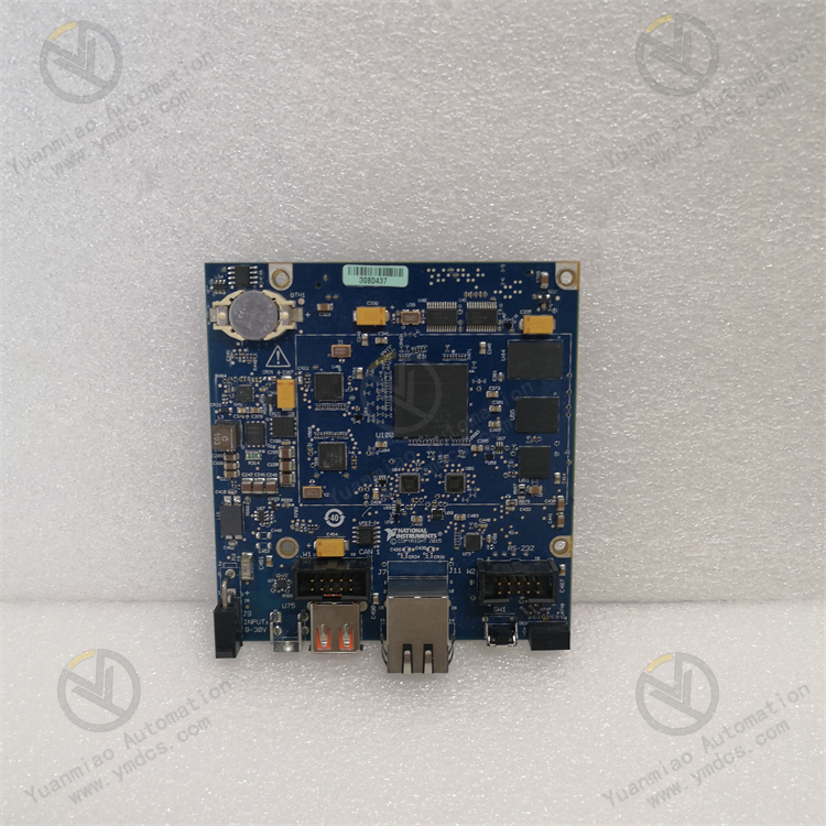
Multi-protocol & Multi-interface Communication & Flexible Data Interaction: Equipped with 2 RS485, 1 Ethernet, and 1 CANopen communication interfaces, it supports mainstream industrial communication protocols such as Modbus RTU, GE Proficy, EtherNet/IP, and CANopen. It can achieve seamless data interaction with upper-level monitoring systems, HMI (Human-Machine Interface), data collectors, PLC (Programmable Logic Controller), and other devices. Remote monitoring and operation & maintenance can be realized through the Ethernet interface. Operation and maintenance personnel can complete module program download, parameter modification, fault diagnosis, and data backup in the central control room without on-site operations, improving operation and maintenance efficiency. It supports multi-module networking communication, which can build a distributed control system to realize collaborative control and centralized management of multiple power equipment in large industrial sites, adapting to the control needs of complex production processes.
Triple Anti-interference Isolation Design & Adaptation to Harsh Environments: It adopts a triple electrical isolation design of "input-output", "input-power", and "inter-channel", with a maximum isolation voltage of 3000VAC/1min, effectively blocking the interference of on-site ground loops, power fluctuations, and equipment electromagnetic radiation on the module. It has built-in EMC (Electromagnetic Compatibility) filter circuits, surge suppression components, and electrostatic protection circuits, which can withstand ±15kV electrostatic discharge shocks and ±2kV pulse burst interference. It has passed IEC 61000-4-2/3/4/6 and other series of anti-electromagnetic interference tests, and can still operate stably in strong interference environments such as high-voltage frequency converters and high-power motors, with RF (Radio Frequency) interference suppression ≥60dB. The sensor input and output interfaces adopt a shielding design, and when used with dedicated shielded cables, the anti-interference performance is further improved.
Industrial-grade Reinforced Structure & Strong Environmental Adaptability: It adopts industrial-grade high-reliability components and an integrated die-cast aluminum alloy shell design. The surface of the shell is treated with anodization and anti-corrosion, which has good heat dissipation, dust-proof, oil-proof, and anti-corrosion performance. The internal heat dissipation structure is optimized, equipped with high thermal conductivity heat dissipation fins and an intelligent temperature-controlled fan, which can quickly dissipate the heat of core components, ensuring the module operates continuously and stably within the standard temperature range of -25~70℃. It has passed the IEC 60068-2-6 vibration test (5~200Hz, 5g acceleration) and IEC 60068-2-27 shock test (20g acceleration, 11ms duration), adapting to equipment operation vibration and transportation/installation shock. The module has an IP20 protection rating, equipped with a dust-proof panel and waterproof aviation connectors to block the intrusion of on-site dust and oil, adapting to harsh environments with heavy dust and high temperature.
Full-dimensional Self-diagnosis & Convenient Operation & Maintenance & Reduced Maintenance Costs: It supports full-dimensional self-diagnosis function, which performs real-time monitoring of power supply voltage, processor status, memory integrity, I/O channel signals, communication links, and redundancy synchronization status. When a fault is diagnosed, the fault type is intuitively displayed through the LED indicators (power, operation, alarm, redundancy status lights) on the front of the module. At the same time, fault codes (such as speed sensor fault E03, analog output short circuit E12) are uploaded through the communication interface, allowing operation and maintenance personnel to quickly locate the fault point through the fault codes. It supports online programming and debugging. Through configuration software, real-time monitoring of the module's operating status, real-time data of I/O channels, and the operation process of control algorithms can be realized, and program modification and parameter calibration can be completed without shutdown. It has built-in program and data backup functions, and backup data can be exported through the communication interface to avoid program loss and reduce maintenance costs.
As the core control unit of the GE Speedtronic series control systems, the GE IS215UCVEM06A module takes "signal collection - preprocessing - logic operation - command output - interlock protection - self-diagnosis - data interaction" as its core workflow to realize full-process precise control and safety protection of large-scale power equipment. The specific working mechanism is as follows:
Module Initialization and Configuration Loading: After the module is installed in the system rack and powered on, it automatically starts the initialization process. First, it performs a hardware self-test, sequentially checking the integrity of the connection between the processor, memory, I/O channels, communication interfaces, redundancy synchronization interfaces, and the rack backplane; after passing the self-test, it establishes communication with the system main controller through the high-speed internal bus of the rack, receives and loads preset configuration parameters and control programs, including I/O channel function configuration, sensor type matching, control algorithm parameters, alarm thresholds, communication protocols, and redundancy configuration information. After the initialization is completed, the module feeds back a "ready" signal to the controller, the operation indicator light remains on, and it enters the normal working mode; if the self-test fails or the configuration loading is incorrect, a fault alarm is triggered immediately, the fault code is uploaded, and the fault indicator light is turned on.
Multi-type Signal Collection and Preprocessing: The module synchronously collects on-site signals through various input channels: the analog channels collect continuous signals such as temperature, pressure, and vibration, which are amplified by an instrumentation amplifier, filtered to remove high-frequency interference by a low-pass filter circuit, and then converted into digital signals by a 16-bit high-precision AD converter; the digital channels collect discrete signals such as solenoid valve status and limit switches, which are converted into standard TTL levels after photoelectric isolation; the pulse channels collect pulse signals from speed sensors, which are converted into recognizable digital pulses after shaping and filtering. All collected signals are sent to the data buffer for temporary storage after preprocessing to ensure signal integrity and stability. At the same time, external interference is blocked through the isolation circuit to protect the safety of internal circuits.
Dual-core Parallel Operation and Control Decision-making: The core processor adopts a dual-core parallel architecture. One core reads the preprocessed signals from the data buffer, performs operation processing according to the loaded control program and algorithms (such as PID regulation and fuzzy control), and calculates the control quantity based on the equipment operating conditions; the other core synchronously performs operation result verification, redundancy data synchronization, and control command generation. Based on the input signal status and preset strategies, the processor generates accurate control commands, such as adjusting the opening of the control valve, controlling the fuel supply quantity, and adjusting the excitation current. In the case of redundancy configuration, the main and standby modules synchronize operation data and control commands in real time through the synchronization bus to ensure output consistency, laying a foundation for disturbance-free switching. The intermediate operation data and results are stored in RAM for monitoring and traceability.
Control Command Output and Execution Monitoring: The processor classifies and sends the control commands to the corresponding output channels: the analog output channels convert the digital control signals into 4~20mA standard signals through a 16-bit DA converter and output them to executive equipment such as control valves and frequency converters; the digital output channels control the action of relays through a relay drive circuit and output discrete signals to solenoid valves, contactors, etc. During the output process, the module collects the actual output status through the feedback circuit and compares it with the command value.
![]()