Description
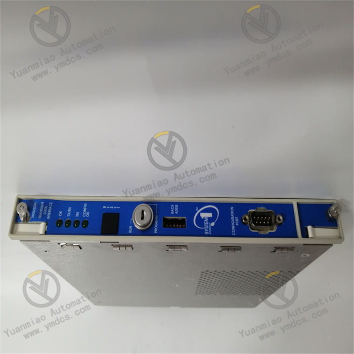
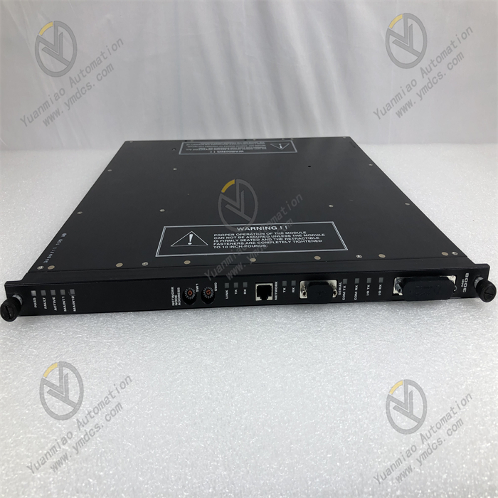
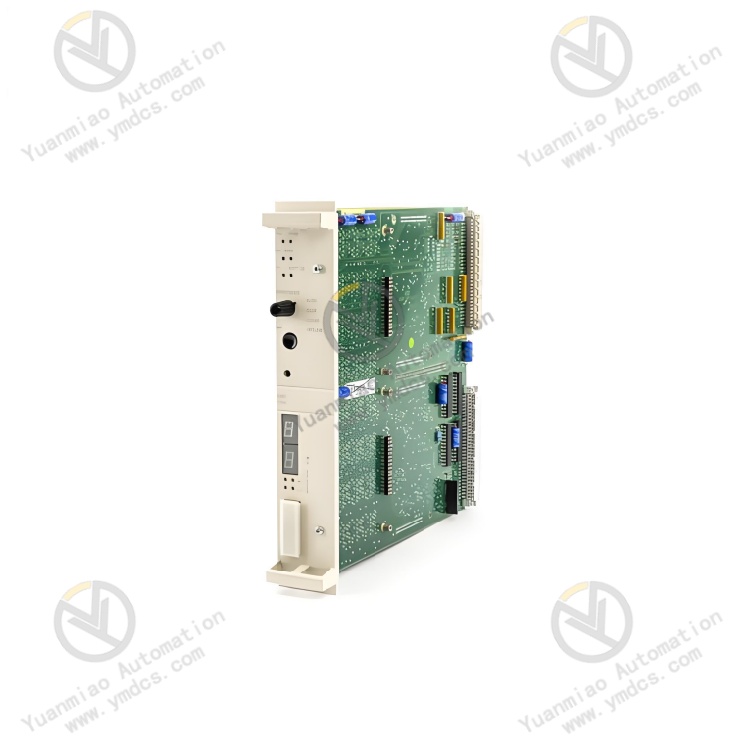
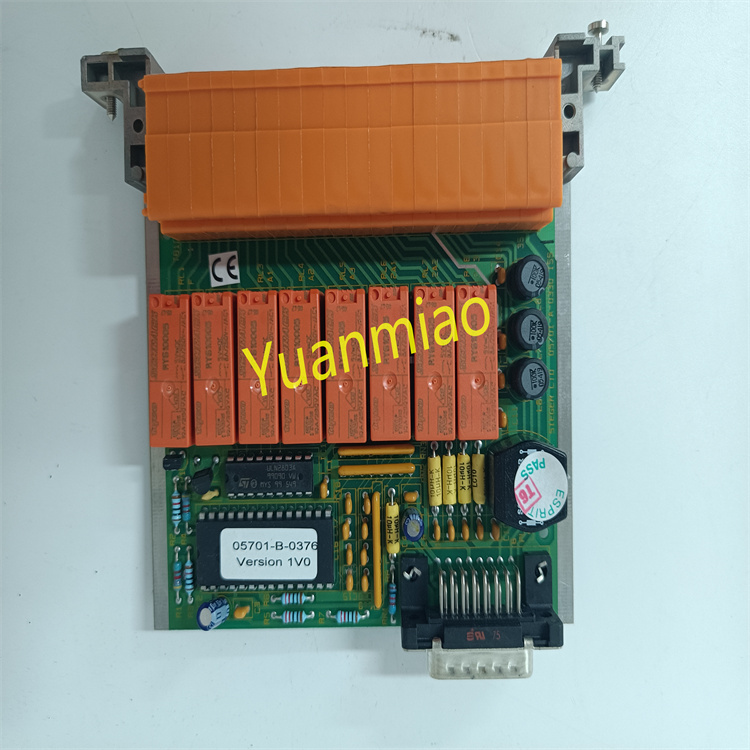
GE 531X304IBDASG1
The GE 531X304IBDASG1 is an industrial-grade high-density digital I/O module launched by General Electric (GE). It belongs to classic industrial control systems such as the GE Mark VIe and Fanuc Series 90-30. Its core positioning is "the core for high-speed digital signal acquisition, logical interlocking, and control command execution in embedded control systems under harsh industrial environments". It mainly serves fields with extremely high requirements for digital signal response speed, anti-interference capability, and environmental adaptability, including power generation equipment status monitoring (e.g., steam turbine valve status, generator excitation system), metallurgical rolling mill equipment interlocking control, chemical process valve switch management, and rail transit signal node control. It undertakes the full-process key tasks of "on-site digital signal (equipment status, sensor feedback) acquisition - logical operation and interlock judgment - control command output (driving actuator) - fault status feedback".
With its core advantages of "high-density digital channel integration + industrial-grade high-reliability hardware architecture + wide-temperature and harsh environment-resistant design + full-system compatibility and adaptation", the module has irreplaceable value in scenarios such as the upgrading of old industrial control systems (e.g., replacing traditional relay control cabinets and discrete digital I/O components) and the construction of new embedded control nodes (e.g., distributed digital control units). Its core role is to solve the three major pain points in industrial control: "high cost of digital channel expansion", "signal misjudgment in complex environments", and "control command execution delay". Through high-speed digital signal processing circuits, enhanced isolation protection design, and standardized system interfaces, it achieves accurate acquisition (response time ≤ 0.5ms) and reliable execution (output action delay ≤ 3ms) of on-site digital signals, avoiding equipment misoperation or production interruption caused by digital module failures (a single interruption can result in losses of up to several hundred thousand yuan) and ensuring the continuous and stable operation of industrial systems.
- High-integration design: A single module integrates 32 inputs + 16 outputs, with channel density increased by 50% compared with traditional modules (most traditional modules have 16 inputs and 8 outputs). For the same channel requirements, it can reduce the number of modules and cabinet installation space (e.g., 256 inputs / 128 outputs only require 8 modules, saving 4 installation positions compared with traditional solutions), and lower system integration costs (hardware cost reduced by 30%, wiring cost reduced by 40%). For example, in the monitoring of large storage tank areas in chemical parks, it is necessary to collect 32 liquid level switches and 16 valve statuses (inputs), and control 16 alarm lights and 8 emergency shut-off valves (outputs); a single module can meet the requirements without splicing multiple modules.
Group configuration and control: Input/output channels are divided into independent units (2 groups of 16 channels for input, 2 groups of 8 channels for output). It supports separate software configuration of input types (dry/wet contact) and output modes (NPN/PNP), adapting to different types of on-site peripherals (e.g., one group of inputs connected to dry-contact liquid level switches, another group connected to wet-contact proximity switches; one group of outputs driving NPN-type solenoid valves, another group driving PNP-type indicator lights). No additional signal conversion modules are required, improving system adaptation flexibility.
- Wide-temperature and harsh environment-resistant design: Core components all adopt industrial-grade wide-temperature models (-40℃ ~ +85℃), and the circuit board is coated with nano-level three-proof paint (waterproof, dustproof, anti-corrosive). It can operate stably in scenarios such as outdoor power control cabinets in Northeast China (winter -35℃), coastal chemical workshops (high humidity and high salt spray), and metallurgical hot rolling workshops (ambient temperature 65℃), with an annual module failure rate ≤ 0.2%. The power module is equipped with a two-stage EMC filter circuit (common mode rejection ratio ≥ 80dB). When installed near high-power frequency converters (above 300kW), the input signal misjudgment rate is ≤ 0.001%, and there is no delay in output actions.
Enhanced isolation and anti-interference: All input/output channels adopt 2500Vrms electrical isolation, with crosstalk attenuation between channels ≥ 90dB, effectively avoiding ground loop interference (e.g., signal mis-triggering caused by ground potential difference of different equipment). Input channels have built-in Schmitt triggers (hysteresis voltage 2V), which can filter out weak interference signals on site (e.g., contact jitter, electromagnetic noise) to ensure reliable signal recognition. Output channels are equipped with overcurrent/short-circuit protection; when the load is short-circuited, the output can be cut off within 10μs to avoid transistor burnout, and it will automatically recover after the fault is eliminated without replacing hardware.
- High-speed signal processing: The input response time is ≤ 0.5ms, which can quickly capture emergency signals such as equipment emergency stop and faults (e.g., pressure switch signals when rolling mills are jammed with steel). Combined with a 5ms operation cycle, the total delay from signal acquisition to output execution of control commands is ≤ 8ms, meeting the real-time requirements of industrial control (e.g., elevator safety protection, high-speed production line interlocking control). The output adopts transistor drive, with a switching frequency of up to 1kHz, supporting high-frequency pulse output (e.g., controlling the speed of stepping motors) and adapting to high-speed control scenarios.
Intelligent logic and interlocking: Built-in rich logical operation functions, supporting multi-channel interlocking (up to 16 input linkages), which can realize "condition combination - command output" automatic control (e.g., "tank liquid level high alarm + pressure high alarm" interlock to close the feed valve and activate the alarm). It does not rely on the computing power of the upper computer, reducing system communication load and delay risks. It supports edge detection (rising/falling edge triggering), which can accurately identify signal state changes (e.g., current switch signals at the moment of motor startup) and avoid logical misjudgment caused by continuous signals.
- Cross-system compatibility and upgrading: Perfectly compatible with GE-series control systems such as GE Mark VIe and Fanuc 90-30, and supports GE Proficy Machine Edition programming software. It can directly call the module's built-in function blocks (DI acquisition block, DO output block, interlocking logic block), shortening the programming cycle from 2 days (traditional solution) to 0.5 days. It is compatible with GE's old digital modules (e.g., 531X302 series), which can directly replace old modules while retaining the original wiring and system programs, reducing the upgrade cost by 50%. It supports interconnection with third-party systems such as Siemens S7-1500 and Rockwell ControlLogix via PROFIBUS DP bus, solving the problem of cross-brand system integration.
Visual operation & maintenance and fault diagnosis: 49 status indicators (32 inputs + 16 outputs + 1 power + 1 bus) are installed on the front panel. On-site personnel can quickly locate problems through the indicators—for example, "a certain input light is not on but the sensor acts" indicates a line or channel fault; "the output light is on but the load does not work" indicates a load or output channel fault. The debugging serial port supports reading real-time data (input/output status, fault logs) via terminal software (e.g., HyperTerminal). The built-in fault log can record the latest 100 fault information (including fault type, occurrence time, and recovery time), shortening the fault location time from an average of 2 hours to 20 minutes and reducing shutdown losses.
![]()