Description
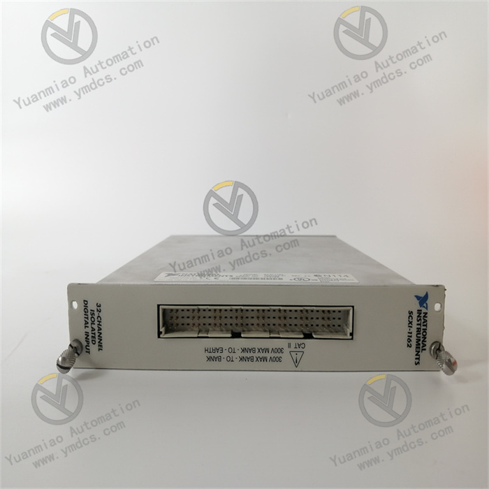
GE 8502-BI-DP
I. Overview
The GE 8502-BI-DP is a high-performance digital input module specifically designed for signal acquisition tasks in industrial automation control systems. As a key component of the GE 8000 Series I/O module family, it features high reliability and high compatibility as its core advantages. It can accurately collect digital signals from industrial sites (such as switch states, equipment start-stop signals, etc.) and achieve high-speed data interaction with controllers via the PROFIBUS-DP fieldbus, providing critical data support for status monitoring and logic control in industrial production processes.
Adopting a modular design and supporting hot-swapping, it can be flexibly adapted to safety controllers such as the GE 8521-LC-MT and 8851-LC-MT series, and is widely used in automation systems of industries including petrochemicals, electric power, food processing, and water treatment. Having passed rigorous industrial-grade testing, this module possesses characteristics such as wide-temperature operation, electromagnetic interference resistance, and vibration protection, enabling stable operation in complex industrial environments. Meanwhile, it is compatible with the installation standards for Class 1, Div 2 hazardous areas. Combined with a comprehensive fault diagnosis function, it can promptly detect and report signal abnormalities, ensuring the accuracy and continuity of system data acquisition, thus becoming a reliable choice for the signal acquisition link in industrial automation.
II. Technical Specifications
(I) Core Performance Parameters
- Input Channels and Types: Provides 16 digital input channels, supporting two input types (PNP/NPN) that can be switched via hardware DIP switches. It is compatible with common two-wire/three-wire sensors in industrial sites (such as proximity switches, photoelectric switches). The input signal voltage range is 24VDC (±10%), meeting the digital signal acquisition needs of most industrial applications.
- Signal Acquisition Accuracy: The input response time is ≤1ms, enabling rapid capture of signal state changes and avoiding control deviations caused by response delays. The signal detection thresholds are 2.5mA (minimum on-current) and 0.1mA (maximum off-current), ensuring that weak signals can also be accurately identified and reducing the risk of misjudgment.
- Communication Capability: Integrates a PROFIBUS-DP communication interface, with an adaptive communication rate ranging from 9.6kbps to 12Mbps, complying with the EN 50170 standard. It supports the DP V1 protocol, enabling periodic data exchange (e.g., upload of input signal states) and non-periodic data interaction (e.g., module parameter configuration, fault diagnosis information reading) with controllers. The bus address can be configured via DIP switches or software (range: 1-126).
(II) Power Supply and Physical Parameters
- Power Requirements: Must be powered by GE 8912-PS-DC or 8913-PS-AC power modules. The input voltage is 24VDC (±10%), the typical operating current is 0.15A (when all channels are in operation), and the maximum power consumption is 3.6W. It supports reverse power connection protection (threshold: -30VDC) to prevent module damage caused by incorrect wiring.
- Dimensions and Weight: The physical dimensions are 48mm (width) × 120mm (length) × 100mm (height). It adopts a DIN rail mounting design and weighs approximately 0.4kg. It can be densely arranged with controllers and other I/O modules of the same series, saving space in control cabinets.
- Environmental Adaptability: The operating temperature range is -40℃ to +70℃, and the storage temperature range is -40℃ to +85℃, with a relative humidity of 5%-95% (non-condensing). Its vibration resistance (10-500Hz, acceleration of 5g, three axes) and shock resistance (15g, 11ms, half-sine wave) comply with the IEC 60068-2 standard, allowing it to adapt to high-temperature, dusty, humid, and vibrating industrial on-site environments.
(III) Expansion and Diagnosis Parameters
- Module Compatibility: Must be installed on a dedicated GE 8750-CA-NS or 8751-CA-NS carrier. It is compatible with GE 8500/8800 Series controllers and supports the formation of a complete I/O system with modules such as the 8511-IO-DC (digital output module) and 8510-HI-TX (analog input module), meeting the needs of multi-type signal acquisition and control.
- Fault Diagnosis: Features a built-in comprehensive diagnosis function that can real-time monitor power faults (e.g., under-voltage, over-voltage), channel faults (e.g., open circuit, short circuit), and communication faults (e.g., bus disconnection, protocol error), and upload fault codes to the controller via the PROFIBUS-DP interface. The module panel is equipped with LED indicators (power light, communication light, channel status light) that can intuitively display the module's operating status and fault location, facilitating quick troubleshooting.
- Isolation Performance: The input channels, power supply, and communication interface adopt an optoelectronic isolation design with an isolation voltage of 2500V AC (for 1 minute), effectively preventing on-site signal interference from entering the control system and ensuring the stable operation of the module and controller. There is no isolation between channels (common ground design), which simplifies wiring while requiring attention to on-site grounding specifications.
III. Functional Features
(I) High-Reliability Signal Acquisition
The GE 8502-BI-DP uses industrial-grade components and optoelectronic isolation technology. Its input channels are equipped with over-voltage and over-current protection functions, capable of withstanding transient voltage surges (e.g., 24VDC signal fluctuating to 30VDC) and avoiding module damage caused by abnormal on-site signals. The fast response time of 1ms ensures timely capture of equipment state changes (such as emergency stop signals in production lines). Combined with accurate signal detection thresholds, it can effectively distinguish between valid signals and interference signals, reducing false alarms or missed alarms and providing accurate and reliable input data for the control system.
(II) Flexible Communication and Integration
Via the PROFIBUS-DP fieldbus, this module can be seamlessly integrated with GE Series controllers or third-party controllers compatible with the PROFIBUS-DP protocol (such as Siemens S7-300/400). The adaptive communication rate function allows it to automatically adjust the transmission speed according to the on-site bus load, avoiding bus congestion. It supports non-periodic data interaction via the DP V1 protocol, enabling maintenance personnel to remotely read module fault information and modify parameters such as input type (PNP/NPN) through the controller or upper computer without disassembling the module on-site, greatly improving maintenance efficiency. The dual bus address configuration methods (DIP switch and software) meet the debugging habits of different on-site scenarios.
(III) Convenient Installation and Maintenance
Support for hot-swapping is a core advantage of this module: during system operation, the module can be directly inserted or removed for replacement or maintenance without stopping the production process, reducing unplanned downtime. The modular design allows for quick assembly with carriers and controllers of the same series, and the DIN rail mounting method simplifies the installation process, enabling even novices to complete deployment quickly. The LED indicators on the panel clearly distinguish the status of the power supply, communication, and channels (e.g., green light on when the channel is on, red light on when a fault occurs). Combined with the fault codes uploaded by the controller, problems (such as a short circuit in a certain channel) can be located within minutes, shortening troubleshooting time.
(IV) Adaptability to Harsh Environments
The GE 8502-BI-DP has been fully optimized for complex industrial on-site environments: its wide-temperature design (-40℃ to +70℃) enables stable operation in extremely cold (e.g., outdoor control cabinets in northern China) or high-temperature (e.g., chemical workshops) environments; its electromagnetic interference resistance can resist electromagnetic radiation generated by high-power on-site equipment (such as frequency converters and motors), preventing interference with signal acquisition; it complies with the Class 1, Div 2 hazardous area standard and can be installed in potentially explosive environments (such as fuel storage areas) without additional explosion-proof enclosures, reducing system integration costs while meeting safety specifications.
(V) High Compatibility and Expandability
This module is compatible with GE 8500/8800 Series controllers and can share carriers with digital output, analog input, and other modules to build a complete I/O system for multi-type signal acquisition and control (e.g., a production line requiring simultaneous acquisition of switch signals and analog signals such as temperature and pressure). It supports PNP/NPN input type switching, allowing adaptation to different types of on-site sensors (such as both PNP-type proximity switches and NPN-type photoelectric switches in a workshop) without replacing the module, reducing inventory costs and replacement difficulty. The 16-channel design can meet the signal acquisition needs of small and medium-sized equipment; if channel expansion is required, it can be achieved by increasing the number of modules without modifying the system architecture.
IV. Application Scenarios
(I) Petrochemical Equipment Status Monitoring
In the safety monitoring system of the storage tank area in an oil refinery, the GE 8502-BI-DP can collect digital signals such as the switch states of valves in the storage tank area (e.g., whether the feed valve and discharge valve are closed in place) and alarm signals from combustible gas detectors (e.g., switch alarms triggered by excessive methane concentration), and upload them to the GE 8851-LC-MT safety controller via the PROFIBUS-DP bus. Its adaptability to hazardous areas ensures reliable operation in flammable and explosive environments, and the optoelectronic isolation technology prevents on-site electromagnetic interference (such as interference from pump motors in the storage tank area), providing accurate input signals for the Emergency Shutdown System (ESD). When it detects that valves are not closed in place or gas alarms are triggered, the controller can promptly activate safety interlocks.
(II) Power Substation Switch Monitoring
In the automation system of a power substation, this module can collect digital inputs such as the opening/closing states of circuit breakers and disconnectors, and the position signals of grounding switches, and transmit them to the background monitoring system via the PROFIBUS-DP bus. Its wide-temperature design enables it to adapt to the low-temperature environment of outdoor control cabinets in substations (e.g., -30℃ in winter), and its vibration resistance can resist slight vibrations during the operation of substation equipment, avoiding signal acquisition interruptions. The module's fault diagnosis function can real-time monitor the channel status; if the acquisition of a circuit breaker status signal is abnormal (such as an open channel), the fault can be quickly located via LED lights and background alarms, facilitating timely maintenance by personnel and ensuring the safe and stable operation of the substation.
(III) Food Production Line Equipment Control
In the baking section of a biscuit production line, the GE 8502-BI-DP can collect digital inputs such as the conveyor belt deviation detection switch (e.g., switch signals triggered when the conveyor belt deviates), oven door limit switch (e.g., signals when the oven door is not closed tightly), and emergency stop button status, and upload them to the GE 8521-LC-MT controller. The hot-swapping function allows faulty modules to be replaced without stopping the production line, avoiding production line shutdown due to module maintenance; the PNP/NPN switching function adapts to different types of detection switches in the workshop, eliminating the need for additional procurement of dedicated modules and reducing costs. When the module detects conveyor belt deviation or an improperly closed oven door, the controller can promptly stop the conveyor belt operation to prevent the production of defective products or safety accidents.
(IV) Water Treatment Plant Pump Group Monitoring
In the aeration tank pump group control system of a sewage treatment plant, this module can collect signals such as the operation status of each water pump (e.g., pump start feedback signal), fault alarm signal (e.g., switch alarm triggered by pump overload), and liquid level switch signal (e.g., signal triggered by excessively high/low liquid level in the aeration tank), and communicate with the controller via the PROFIBUS-DP bus. Its moisture resistance enables it to adapt to the humid working environment of the water treatment plant, avoiding module faults caused by moisture; the 16 channels can simultaneously collect dual signals (operation + fault) of 8 water pumps, reducing the number of modules and saving space in the control cabinet. When a water pump fails, the module can quickly upload the fault signal to the controller, which automatically switches to a standby water pump to ensure uninterrupted oxygen supply to the aeration tank and guarantee the sewage treatment effect.
V. Common Faults and Troubleshooting Methods
(I) No Power Supply to the Module or Power Light Not On
Possible Causes:
- Loose or disconnected power wiring (e.g., poor contact at the module's power terminals);
- Abnormal output voltage of the power module (e.g., 24VDC power fluctuating below 18VDC, which is lower than the module's minimum operating voltage);
- Faulty power interface of the module (e.g., damaged internal power chip).
Troubleshooting Methods:
- Check the wiring of the module's power terminals, reinsert and fasten the terminals to ensure good contact between the power cable and the terminals;
- Use a multimeter to detect the output voltage of the power module and confirm it is within the range of 24VDC±10%. If the voltage is abnormal, replace the power module or check the front-end power supply;
- If the power wiring and voltage are normal, test with a spare module. If the power light of the spare module is on, it is determined that the power interface of the original module is faulty. Contact GE after-sales service for repair or replacement.
(II) Communication Fault (Communication Light Not On or Blinking)
Possible Causes:
- Loose or damaged PROFIBUS-DP bus cable (e.g., poor contact at the bus terminals, cable chewed by rats);
- Incorrect bus address setting (e.g., the module's DIP switch address is inconsistent with the controller's configured address);
- Unconfigured bus terminal resistor (120Ω terminal resistors need to be installed on the modules at both ends of the bus, no installation required for intermediate modules);
- Faulty communication interface (e.g., damaged internal PROFIBUS-DP chip of the module).
Troubleshooting Methods:
- Check the wiring of the bus cable, reinsert the bus terminals, use a multimeter to detect the continuity of the cable, and replace the cable if there is damage;
- Verify that the module's DIP switch address is consistent with the controller's configured address (e.g., if the DIP switch is set to 5, the controller should be configured with address 5). If inconsistent, adjust the DIP switch or controller parameters;
- Check whether 120Ω terminal resistors are installed on the modules at both ends of the bus. If missing, install additional resistors and measure the resistance to ensure it is approximately 120Ω;
- If the above operations are ineffective, test with a spare module. If the communication of the spare module is normal, the communication interface of the original module is faulty and needs to be repaired or replaced.
(III) No Signal Input to One or Multiple Channels (Channel Light Not On)
Possible Causes:
- Faulty on-site sensor (e.g., damaged proximity switch with no 24VDC signal output);
- Loose or short-circuited channel wiring (e.g., poor contact of the sensor cable, short circuit caused by damaged insulation layer of the cable);
- Mismatch between the module's input type and the sensor (e.g., the module is set to PNP input while the sensor is NPN output, preventing signal conduction);
- Internal fault of the module channel (e.g., damaged optocoupler).
Troubleshooting Methods:
- Use a multimeter to detect the output end of the sensor and confirm there is a 24VDC signal (PNP sensors output 24VDC when turned on, while NPN sensors output 0V when turned on). If the sensor has no output, replace the sensor;
- Check the channel wiring terminals, reinsert the cables, and use a multimeter to detect whether the cable is short-circuited (e.g., a cable with a resistance of 0Ω between its two ends is short-circuited). Repair or replace the cable if there is a short circuit;
- Check the module's DIP switch to confirm that the input type (PNP/NPN) matches the sensor. If not, adjust the DIP switch (e.g., set DIP switches 1-2 to 01 for PNP, 10 for NPN);
- If the sensor, wiring, and input type are all normal, connect the sensor cable of the faulty channel to a normal channel for testing. If the normal channel can detect the signal, the original channel is faulty, and the module needs to be replaced.
(IV) False Triggering of Channel Signals (Channel Light Turning On Unreasonably)
Possible Causes:
- On-site electromagnetic interference (e.g., the module is close to high-power equipment such as frequency converters and motors, and electromagnetic radiation causes false signals);
- Poor grounding of the sensor cable (e.g., the cable's shielding layer is not grounded, allowing interference signals to enter);
- Excessively low module input threshold setting (e.g., some modules support threshold adjustment, which is incorrectly set to 0.05mA, allowing weak interference signals to trigger the channel);
- Leakage in the module channel (e.g., poor insulation of the internal circuit, causing slight leakage to trigger channel conduction).
Troubleshooting Methods:
- Keep the module at least 30cm away from high-power equipment, or cover the sensor cable with a metal shielding tube to reduce electromagnetic interference;
- Check the grounding of the sensor cable's shielding layer, ensuring single-end grounding (e.g., grounding only at the control cabinet end) to avoid loop current caused by double-end grounding;
- If the module supports input threshold adjustment (some models via software configuration), restore the threshold to the default value (e.g., 0.1mA) to enhance anti-interference capability;
- Test with a spare module. If the spare module has no false triggering, the original module has channel leakage and needs to be repaired or replaced.