Description
GE IC698PSA350D
I. Overview
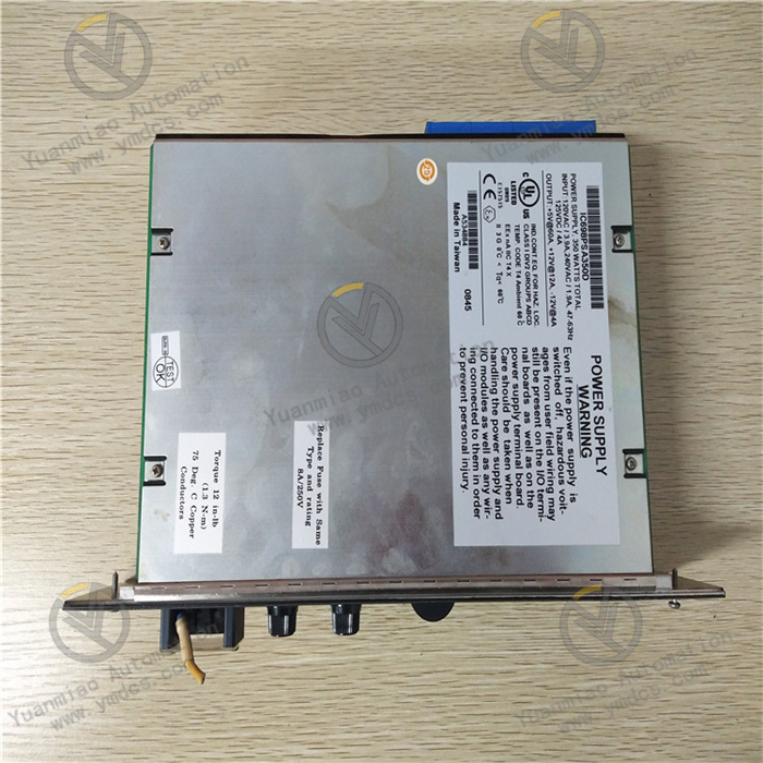
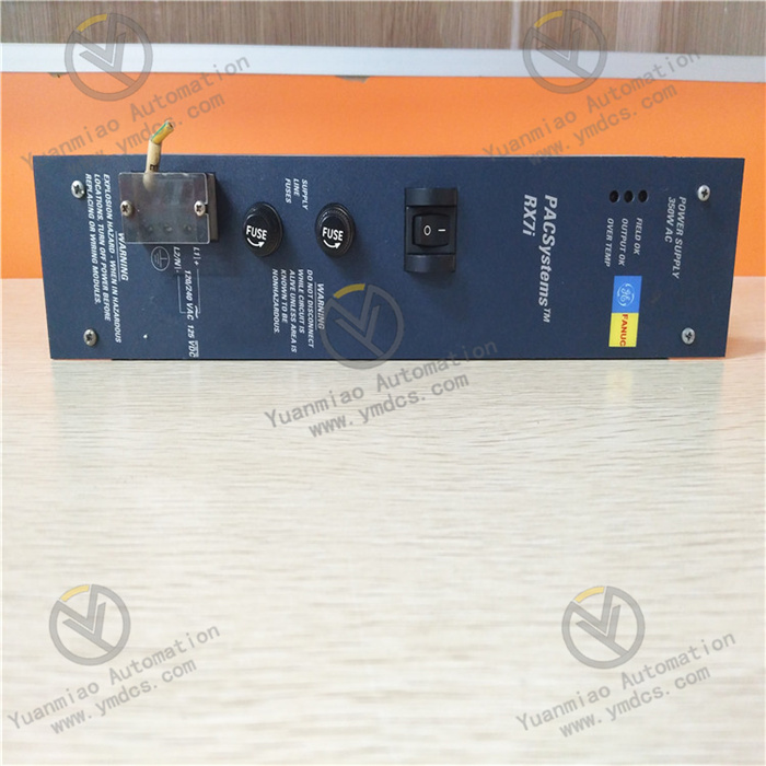
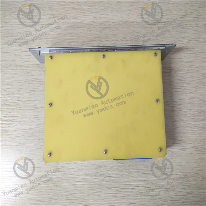
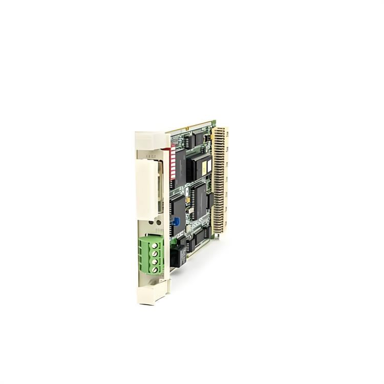
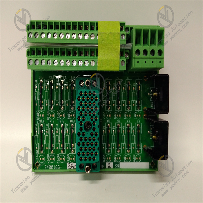
The GE IC698PSA350D is a redundant switching power supply module developed to meet the "high-reliability centralized power supply" requirement of industrial automation control systems. It belongs to the GE RX3i series of automation products, with its core positioning being to provide stable and efficient DC power supply for industrial PLCs, DCS systems, and peripheral equipment (such as sensors and actuators). It undertakes an integrated role of "AC-to-DC conversion + redundant backup + overload protection + fault early warning". This module is widely used in industrial scenarios with strict requirements on power supply stability, redundancy, and environmental adaptability, including power supply for PLC control cabinets in petrochemical production equipment, power distribution for auxiliary control systems in thermal power plants, power supply for automation equipment in metallurgical steel rolling production lines, power support for control systems in municipal water treatment plants, and power supply for core PLC components in high-end equipment manufacturing.
II. Technical Parameters
| Parameter Category | Specific Specifications | Remarks |
|---|---|---|
| Input Parameters | Input Voltage: 85-264V AC (single-phase), 47-63Hz | Wide-voltage design, compatible with power grids in different regions around the world (e.g., 220V AC in China, 110V AC in the United States), avoiding the impact of power grid voltage fluctuations |
| Input Current: Maximum 8A (115V AC), 4A (230V AC) | Low input current design to reduce power grid load | |
| Power Factor: ≥0.95 (at full load) | High power factor to reduce reactive power loss, meeting industrial energy-saving requirements | |
| Input Protection: Overvoltage protection (triggered at 280V AC), undervoltage protection (triggered at 80V AC), surge protection (±4kV line-to-ground) | Resists overvoltage, undervoltage, and surge impacts of the power grid to protect the internal circuit of the module | |
| Output Parameters | Output Voltage: 24V DC ±1% | High-precision output, meeting the power supply needs of precision equipment such as PLCs and sensors |
| Output Current: Maximum 14.6A (24V DC) | Output power of 350W, capable of powering multiple devices simultaneously (e.g., 10 pcs of 4-20mA sensors + 5 pcs of small actuators) | |
| Output Ripple: ≤50mV P-P | Low-ripple output, avoiding noise interference with PLC signal processing | |
| Output Protection: Overcurrent protection (triggered at 16A, hiccup mode), short-circuit protection (automatic recovery), overtemperature protection (triggered at 75°C) | Multi-dimensional protection for downstream equipment, preventing damage caused by overload and short circuit | |
| Redundancy Characteristics | Redundancy Mode: Supports 1+1 or N+1 redundant parallel connection | Automatic current sharing when multiple modules are connected in parallel, with load sharing error ≤5%. A single module failure does not affect the overall power supply |
| Redundancy Switching Time: ≤1ms | Unnoticeable switching of faulty modules to ensure uninterrupted power supply | |
| Physical & Environmental Parameters | Casing Material: Cold-rolled steel plate (with anti-corrosion powder coating on the surface) | Impact resistance ≥100N, suitable for installation environment inside industrial control cabinets |
| Dimensions: 190mm × 140mm × 85mm (Length × Width × Height) | Compact design, suitable for installation in standard 19-inch industrial cabinets | |
| Weight: Approximately 1.8kg | Lightweight structure, facilitating stacked installation of modules inside the cabinet | |
| Operating Temperature: 0°C to +60°C, Storage Temperature: -40°C to +85°C | Wide-temperature design, adapting to high-temperature environments in industrial workshops (e.g., metallurgical workshops) | |
| Heat Dissipation Method: Natural heat dissipation + heat sink-assisted heat dissipation | Fanless design, avoiding heat dissipation failures caused by dust blockage and improving reliability |
III. Functional Features
1. Wide Input Range and High-Precision Output
2. Flexible Redundant Parallel Connection and Current Sharing Control
3. Multi-Dimensional Protection and Fault Early Warning
4. High Reliability and Adaptability to Industrial Environments
5. Convenient Installation and System Integration
IV. Common Faults and Solutions
| Fault Phenomenon | Possible Causes | Solutions |
|---|---|---|
| 1. No output voltage after the module is powered on, and the power indicator is off | 1. Input power supply disconnection or loose wiring terminals; 2. Input voltage exceeds the range (e.g., lower than 85V AC or higher than 264V AC); 3. Damaged internal power chip of the module; 4. Burned input fuse | 1. Use a multimeter to measure the continuity of the AC input line, check the wiring of L, N, and PE terminals, re-tighten them, and ensure correct wiring; 2. Measure the input voltage. If the voltage is abnormal, check the external power grid or transformer to ensure the voltage is within the range of 85-264V AC; 3. If there is still no output when the input voltage is normal, contact GE-authorized maintenance personnel to check whether the internal switching power supply chip (such as TI UCC28070) is burned and replace the damaged components; 4. Check the internal fuse of the module (usually 5A/250V). If it is burned, replace it with a fuse of the same specification (GE original accessories are recommended) |
| 2. Large deviation of output voltage, exceeding the range of ±1% | 1. Too light output load (lower than 10% of rated load); 2. Faulty internal voltage feedback circuit of the module; 3. Poor contact of output terminals or excessive line impedance; 4. Component aging caused by long-term operation of the module | 1. Increase the output load to more than 10% of the rated load (e.g., connect multiple sensors) and test whether the voltage returns to normal; 2. Contact maintenance personnel to check the voltage feedback circuit (such as optocoupler PC817, error amplifier TL431) and replace the faulty components; 3. Check the wiring of the output terminals, re-tighten the terminals, and replace the wires with a thicker diameter (e.g., replace 16AWG with 10AWG) to reduce line impedance; 4. If the module has been used for more than 5 years, it is recommended to replace it with a new one to avoid output instability caused by component aging |
| 3. Uneven load sharing during redundant parallel connection, and one module is overloaded | 1. Current sharing control lines between redundant modules are not connected or have poor contact; 2. Faulty current sharing control circuit of the module; 3. Inconsistent firmware versions of redundant modules; 4. Unreasonable output load distribution | 1. Check the current sharing control lines between modules (usually RJ45 interface), re-plug and fasten them to ensure smooth lines; 2. Test the output current of each module individually. If the current of a module is abnormal, check its current sharing control chip (such as ADI AD8410) and replace the faulty components; 3. Upgrade the firmware of all redundant modules to the same version through GE Proficy software to ensure consistent current sharing algorithms; 4. Re-distribute the output load to avoid excessive load on one line (it is recommended that the load of a single line does not exceed 80% of the module's rated output) |
| 4. The module frequently triggers overtemperature protection, and the fault light flashes | 1. The operating environment temperature exceeds the range of 0°C-60°C; 2. Excessive dust accumulation on the module's heat sink leads to poor heat dissipation; 3. Insufficient number of redundant modules, resulting in excessive load on a single module; 4. Faulty internal cooling fan (if equipped) of the module (for some models) | 1. Check the temperature inside the cabinet. If the temperature is too high, install industrial air conditioners or cooling fans to reduce the environmental temperature to below 60°C; 2. Use compressed air (0.3MPa) to blow off the dust on the heat sink and clean the heat dissipation channel; 3. Increase the number of redundant modules (e.g., change 1+1 redundancy to 2+1 redundancy) to reduce the load rate of a single module (it is recommended that the load rate ≤70%); 4. If the module is equipped with a cooling fan, check the fan's operation status and replace it with a fan of the same specification (such as Nidec 4020 series) if it is faulty |
| 5. The module cannot recover automatically after output short circuit, and there is no output | 1. The short-circuit fault is not eliminated, and the module continuously triggers protection; 2. Faulty short-circuit protection circuit of the module (such as burned overcurrent detection resistor); 3. The module enters the "lockout protection" mode and requires manual reset | 1. Disconnect all output loads, use a multimeter to measure the resistance between the output terminals, check the short-circuit point (such as damaged wire insulation), and repair the short-circuit fault; 2. If there is still no output after the short-circuit fault is eliminated, check the internal overcurrent detection resistor of the module (such as 0.1Ω sampling resistor). If it is burned, replace it with a resistor of the same specification; 3. Disconnect the module's input power supply for 30 seconds and then power it on again to release the "lockout protection" mode and test whether the output is restored to normal |


