Description
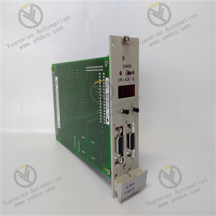
GE 8724-CA-PS
I. Overview
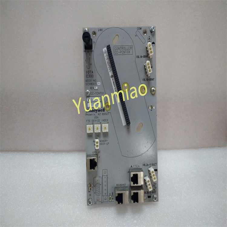
The GE 8724-CA-PS is an industrial-grade compact DC power supply module, mainly compatible with GE industrial automation control systems (such as Mark series control systems, PLC systems, etc.). It provides stable DC power supply for low-voltage equipment including core control units, sensors, and actuators. Its design focuses on "high stability" and "strong environmental adaptability", and adopts an isolated power supply architecture, which can effectively suppress electromagnetic interference (EMI) and voltage fluctuations in industrial sites. It is widely used in scenarios with strict requirements on power supply reliability, such as energy (thermal power, wind power), chemical industry, metallurgy, and intelligent manufacturing.
Compared with ordinary industrial power supplies, this module has the characteristics of "wide input voltage range", "multiple protection mechanisms" and "modular compatibility". It can be directly integrated into GE standard control cabinets to reduce the complex wiring of external power supplies. At the same time, it supports parallel expansion of multiple modules to meet the power requirements of different loads.
II. Technical Parameters
1. Basic Specifications
| Item | Parameter Details |
|---|---|
| Overall Dimensions | 120mm (Length) × 80mm (Width) × 40mm (Height) (compact design) |
| Weight | Approximately 0.25kg |
| Operating Temperature Range | -10°C ~ 60°C (operation); -40°C ~ 85°C (storage) |
| Protection Level | IP20 (panel-mounted, protection against solid foreign objects) |
| Installation Method | DIN rail mounting (compatible with 35mm standard industrial rails) |
2. Electrical Performance
Input Parameters:
- AC input voltage range: 100V AC ~ 240V AC (wide-range adaptation, compatible with single-phase commercial power/industrial power);
- Input frequency: 50Hz ~ 60Hz (self-adaptive, no manual switching required);
- Input current: Maximum 1.5A (at 220V AC full load);
- Power factor: ≥0.9 (at full load, reducing reactive power loss).
Output Parameters:
- Output voltage: 24V DC (fixed output, accuracy ±2%);
- Rated output current: 4A (continuous output);
- Peak output current: 6A (short-term overload, duration ≤10s);
- Output ripple and noise: ≤50mVp-p (when outputting 24V, effectively suppressing voltage fluctuations);
- Efficiency: ≥88% (under conditions of 220V AC input and full load, saving energy and reducing consumption).
Isolation Characteristics:
- Input-output isolation voltage: 2500V AC (for 1 minute, preventing high-low voltage crosstalk);
- Output-ground isolation voltage: 1500V AC (for 1 minute, improving anti-interference capability).
3. Protection Performance Parameters
| Protection Type | Trigger Condition | Recovery Method |
|---|---|---|
| Overcurrent Protection (OCP) | Output current > 6.5A (for 0.5s continuously) | Automatic recovery after overload is removed |
| Overvoltage Protection (OVP) | Output voltage > 28V DC | Module restart required after overvoltage is removed |
| Overtemperature Protection (OTP) | Internal module temperature > 85°C | Recovery when temperature drops below 70°C |
| Short-Circuit Protection (SCP) | Short circuit at output terminal (impedance < 0.5Ω) | Automatic recovery after short circuit is removed |
III. Functional Features
1. Wide-Range Adaptation and High Stability
- Wide input voltage + frequency self-adaptation: The input range of 100V~240V AC covers most industrial power scenarios worldwide, and the 50/60Hz frequency is self-adaptive. No parameter adjustment is required for different regions, reducing the complexity of on-site debugging;
- Low ripple output: The output ripple is ≤50mVp-p. Equipped with a built-in EMI filter, it can effectively suppress electromagnetic interference caused by motor start-stop and frequency converter operation in industrial sites, and prevent misoperation of control units due to voltage fluctuations.
2. Multiple Safety Protection Mechanisms
- Full-scenario protection coverage: Integrates four types of protection, including overcurrent, overvoltage, overtemperature, and short-circuit protection. The overcurrent/short-circuit protection supports "automatic recovery", reducing on-site restart operations; the overvoltage/overtemperature protection adopts a dual logic of "hardware trigger + software backup" to avoid protection failure caused by a single fault;
- Isolation design: Dual isolation between input-output and output-ground prevents high voltage from entering the control circuit, protecting downstream precision equipment (such as sensors and PLC modules) from voltage shocks.
3. Convenient Installation and Operation & Maintenance
- Quick DIN rail installation: Compatible with 35mm standard industrial rails, no drilling is required during installation. A single person can fix the module, which is suitable for the layout of GE standard control cabinets;
- Visual status indication: Two LED indicators are installed on the front - "Power Normal" (green, constant on indicates normal input and output) and "Fault Alarm" (red, flashing/constant on indicates overvoltage/overtemperature/overload). The working status of the module can be quickly judged without disassembly;
- Modular expansion: Supports parallel operation of multiple modules (up to 4 modules in parallel). After parallel connection, the total output current can be expanded to 16A (24V DC), and it has a "current sharing function" to avoid overload of a single module and meet the growing power demand of loads.
4. Industrial-Grade Environmental Tolerance
- Wide temperature operating range: The operating temperature of -10°C~60°C covers most industrial workshops (such as high-temperature metallurgical workshops and low-temperature wind power control cabinets), and the storage temperature is as low as -40°C, which is suitable for transportation and temporary outdoor storage scenarios;
- Vibration and shock resistance: Complies with IEC 60068-2-6 vibration standard (10~500Hz, acceleration 5g) and IEC 60068-2-27 shock standard (acceleration 30g, duration 11ms), adapting to mechanical vibrations during equipment operation (such as cabinet vibrations driven by motors and pumps).
IV. Common Faults and Troubleshooting Methods
| Fault Phenomenon | Possible Causes | Troubleshooting Measures |
|---|---|---|
| Green "Power Normal" light not on, no output | 1. Input voltage not connected/abnormal input voltage (<100V or >240V); 2. Input line open circuit/loose terminal connections; 3. Faulty internal power chip of the module | 1. Use a multimeter to detect the input voltage and confirm it is within the range of 100~240V AC; 2. Check the wiring of the input terminals (L/N poles) and re-tighten the screws; 3. If there is still no output when the input is normal, replace the module with the same model (faults of internal chips are mostly irreversible) |
| Red "Fault Alarm" light constantly on (overvoltage) | 1. Instantaneous high input voltage (such as power grid surge); 2. Abnormal voltage feedback caused by faulty external equipment at the output terminal; 3. Mis-triggering of the internal overvoltage protection circuit of the module | 1. Disconnect the input power, restart after 5 minutes, and observe whether the alarm is cleared (overvoltage caused by surges is mostly temporary); 2. Disconnect all downstream loads and test the module output independently (if the output returns to normal, it indicates a fault in the load equipment, and the load needs to be checked); 3. If the alarm persists after restart, return the module to the factory to calibrate the overvoltage protection threshold or replace the module |
| Red "Fault Alarm" light flashing (overtemperature) | 1. Ambient temperature around the module > 60°C (such as poor ventilation of the control cabinet, proximity to heat-generating equipment); 2. Blocked heat dissipation channels of the module (covered with dust); 3. Internal heat accumulation caused by long-term full-load operation | 1. Check whether the ventilation fan of the control cabinet is operating normally. If the ambient temperature is too high, install an additional cooling fan or remove heat-generating equipment near the module; 2. After power-off, use compressed air to clean the dust on the module surface and heat dissipation holes; 3. If overtemperature is caused by full-load operation, add parallel modules to share the load (e.g., two 4A modules in parallel to replace the requirement of one 8A module) |
| Insufficient output current, load cannot start | 1. Load power exceeds the rated output of the module (>4A continuous load); 2. Failure of the current sharing function when modules are in parallel (multi-module parallel scenario); 3. Excessive output line resistance (too thin cables/oxidized terminals) | 1. Calculate the total load power (P=24V×I) and confirm it does not exceed the rated power of the module (96W). If overloaded, add parallel modules; 2. Check whether the "current sharing control lines" of the parallel modules are properly connected (some models require dedicated current sharing lines), and re-plug the current sharing terminals; 3. Replace the output cables with a cross-sectional area of ≥1.5mm², polish the oxidized terminals with sandpaper, and re-tighten them |
| Excessive output ripple, misoperation of downstream equipment | 1. Failure of the built-in EMI filter of the module; 2. Output cables not using shielded wires, subject to external electromagnetic interference; 3. Load is a "pulsed load" (e.g., frequent start-stop of solenoid valves) | 1. Use an oscilloscope to detect the output ripple. If it is >50mVp-p, replace the built-in filter of the module (or return it to the factory for repair); 2. Replace the output cables with shielded layers, and ground one end of the shielded layer (connect to the control cabinet ground bar); 3. Connect a 1000μF/25V electrolytic capacitor in parallel at both ends of the pulsed load to suppress instantaneous current fluctuations |