Description
GE IS215ACLEH1BB
I. Overview
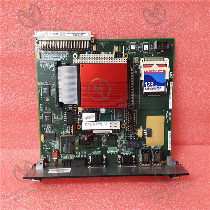
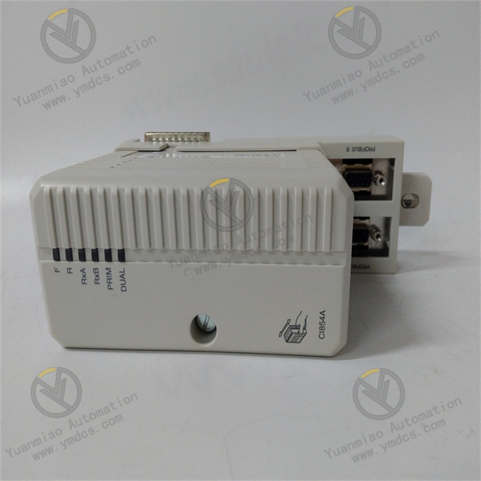
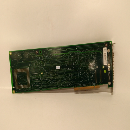
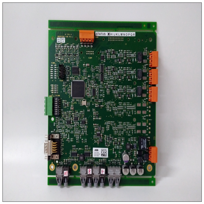
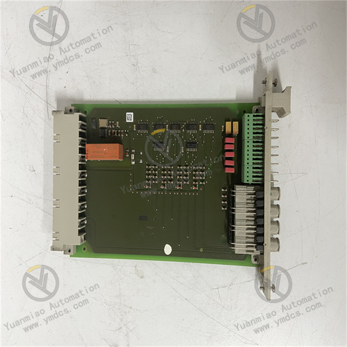
GE IS215ACLEH1BB is an Application Control Layer (ACL) module of the EX2100 series. As a microprocessor-based main control unit, it is deeply integrated into the GE EX2100 control system and primarily undertakes the functions of "control command execution - multi-source data processing - cross-network collaboration". It is applicable to industrial fields such as power generation (e.g., steam turbine drive control), oil and gas (e.g., pump station speed regulation), and water treatment (e.g., motor cluster management and control). It can realize centralized control of underlying drives, exciters, and sensors via Ethernet and ISBus, while connecting upward to monitoring systems like SCADA. It serves as a key hub linking the "on-site execution layer - control layer - monitoring layer".
Compared with the IS215ACLEH1AB of the same series and ordinary control modules, this module has three core advantages:
- Hardware detail optimization: Adjustments have been made to the definition of some interface pins and signal isolation circuits to enhance the anti-interference capability of digital signals;
- Expanded deployment scenarios: In addition to being compatible with the EX2100 exciter system and Inovance series drives, it can also work with some early GE industrial drive racks, reducing the upgrade cost of aging systems;
- Enhanced firmware compatibility: It supports the latest firmware version of the EX2100 system, optimizes the response speed of multi-module collaborative control, and is suitable for high-complexity industrial control logic.
II. Technical Parameters
1. Basic Specifications
| Item | Parameter Details |
|---|---|
| Equipment Type | Application Control Layer (ACL) Module, Main Controller Module |
| Compatible Systems | GE EX2100 Control System, Inovance Series Drives, EX2100 Exciter System, some early GE industrial drive systems |
| Installation Method | Standard rack mounting (occupies 2.5 slots, compatible with EX2100 standard rack rails) |
| Deployment Compatibility | Supports Control Assembly Backplane (CABP), Exciter Backplane (EBKP), and dedicated backplanes for early drive systems |
| PCB Protection | Conformal coating (moisture-proof, anti-corrosion, dust-proof, compliant with IEC 60068-2-10 humidity standard) |
| Operating Temperature Range | -30°C ~ 65°C (operation); -40°C ~ 85°C (storage) |
| Power Supply Requirement | 5V DC power supply, rated current 3.0A (peak current 3.5A, lasting 5s) |
2. Hardware Parameters
Processor and Storage Architecture
- CPU Configuration: 266MHz high-performance microprocessor running QNX4 real-time operating system, supporting multi-task priority scheduling (response time of the highest-priority task < 1ms) to meet the real-time requirements of industrial control;
- Storage Capacity: 128KB Level 2 Cache (L2 Cache) for accelerating instruction and data access; 8MB DRAM temporary data storage (supporting data power-off protection, maintaining 10ms data backup via capacitor); 4MB flash BIOS (supporting local upgrade via P3 interface or remote upgrade via Ethernet);
- Expanded Storage: The P3 interface supports a maximum of 128MB CompactFlash (CF) card, which can store control programs, fault logs, and configuration parameters to meet the program storage needs of complex control logic.
Interface and Communication Characteristics
| Interface Type | Specification Parameters | Function Purpose |
|---|---|---|
| Main Connector | P1 connector (4 rows, 128 pins, gold-plated contacts, anti-oxidation) | Connects to the system backplane (CABP/EBKP) to realize power input, data interaction, and inter-module synchronization |
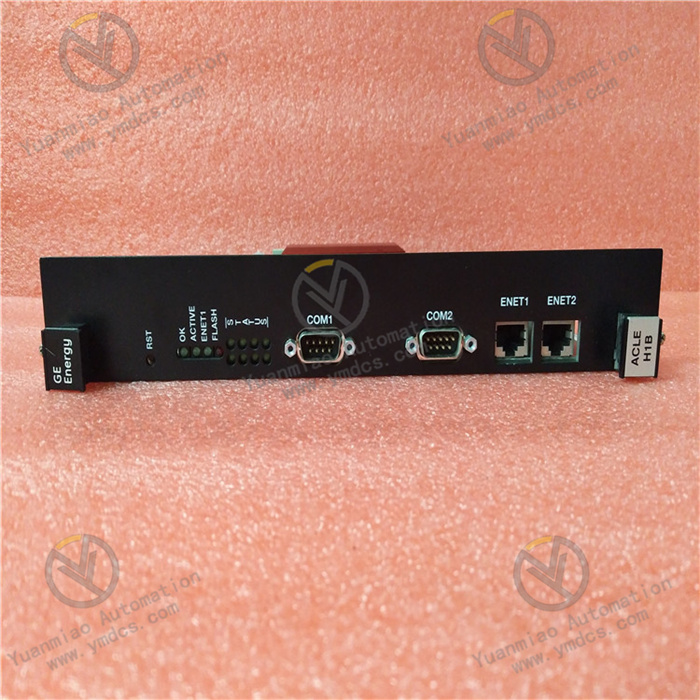
| Ethernet Interface | ENET 1/ENET 2 dual ports (RJ45 interface, 10/100Mbps auto-negotiation) | Supports TCP/IP protocol for remote monitoring, program downloading, and connection with SCADA systems; dual ports support link redundancy to avoid communication interruption |
| Serial Ports | COM1/COM2 dual asynchronous serial ports (switchable between RS232/RS485) | Connects to debugging terminals, printers, or underlying sensors; supports Modbus RTU protocol for communicating with legacy devices |
| Dedicated Function Interfaces | P6 reset interface (hardware reset button + remote reset signal input), P8 status indicator interface | Resets the module locally/remotely; external indicator lights show the module's operating status (power, communication, fault) |
| Bus Interface | ISBus bus target interface (rate 1Mbps) | Synchronizes data with drives and I/O modules in the EX2100 system, and coordinates control logic (e.g., issuing drive speed regulation commands) |
Signal Processing and Anti-Interference
- Digital Signal Processing: Supports expansion of 16-channel digital input (DI) and 8-channel digital output (DO) (by connecting expansion modules via backplane bus); the filtering time of input signals is configurable (0.1ms ~ 100ms) to suppress high-frequency interference;
- Anti-Interference Design: The power input end has a built-in EMI filter (compliant with EN 55022 Class B radiation standard); the signal circuit adopts photoelectric isolation (isolation voltage 2500V AC for 1 minute); PCB layout is optimized, with analog and digital circuits routed separately to reduce crosstalk;
- Mechanical Stability: The module housing adopts a metal reinforcing rib design; its anti-vibration performance complies with IEC 60068-2-6 standard (10-500Hz, acceleration 2g, lasting 10min/axis), adapting to the vibration environment of industrial sites.
III. Functional Features
1. Multi-Scenario Adaptation and Hardware Optimization
- Cross-System Deployment Compatibility: It is not only compatible with the new-generation EX2100 exciter and drive systems but also can be connected to early GE industrial drive racks (e.g., 1990s series drives) via backplane adaptation kits. This enables control upgrades for aging equipment without replacing the entire control system, reducing transformation costs;
- Enhanced Interface Performance: The dual Ethernet ports support link aggregation and redundancy. When a port or network cable fails, it can automatically switch to the standby port (switching time < 50ms) to ensure uninterrupted communication with the monitoring system; the serial ports support software switching between RS232/RS485 modes without hardware jumpers, adapting to peripheral devices with different communication distances (maximum RS485 communication distance is 1200m);
- Improved Power Supply Adaptability: The 5V DC power supply supports ±10% voltage fluctuation (4.5V ~ 5.5V), adapting to scenarios with unstable power supply voltage in industrial sites (e.g., power grid fluctuations during power plant start-up and shutdown). It also has a built-in overcurrent protection (threshold 4A) to prevent module burnout due to power supply faults.
2. Intelligent Control and Collaborative Capability
- Multi-Task Control Logic: Based on the QNX4 real-time operating system, it can run multiple tasks simultaneously, such as "drive speed regulation control", "excitation adjustment", and "fault diagnosis". Task priorities can be configured (e.g., the "emergency shutdown" task is set to the highest priority with a response time < 1ms), meeting the multi-objective control needs of complex industrial scenarios;
- Data Processing and Forwarding: It supports collecting data from underlying sensors (e.g., temperature, pressure) and drive status data (e.g., speed, current). After local filtering and threshold judgment, the data is uploaded to the SCADA system via Ethernet on the one hand, and control commands (e.g., adjusting excitation current, changing drive speed) are issued via the ISBus on the other hand, forming a "data collection - processing - control" closed loop;
- Inter-Module Collaborative Control: It can work collaboratively with EX2100 series I/O modules (e.g., IS200IOCCH1A) and communication modules (e.g., IS200COMMH1A) via the backplane bus. For example, when the I/O module detects "excessively high bearing temperature", it can trigger the IS215ACLEH1BB module to execute "speed reduction" or "shutdown" commands without intervention from the upper computer, improving control response speed.
3. Fault Diagnosis and Maintenance Convenience
- Comprehensive Fault Monitoring: It has a built-in fault detection circuit that can identify 12 types of faults, such as "power overvoltage/undervoltage", "Ethernet communication interruption", "ISBus fault", and "flash read/write error". Fault codes (e.g., F02 for power undervoltage, F10 for ISBus communication timeout) are sent to the monitoring system via the ENET interface, and the external fault indicator light (red, steady on) of the P8 interface is triggered simultaneously;
- Fault Logging and Tracing: It supports storing up to 500 fault logs (including fault type, occurrence time, and key parameter values at the time of the fault, such as speed and current). The logs are not lost when power is off and can be exported via Ethernet or CF card, facilitating maintenance personnel to analyze the cause of faults (e.g., determining whether a shutdown is caused by "abnormal excitation current");
- Convenient Maintenance Design: The P6 interface supports local hardware reset (button) and remote software reset (via commands issued by the monitoring system). When the module has faults such as "program crash", it can be reset remotely without on-site operation; configuration parameters can be read/modified locally via the P3 interface without disassembling the module, reducing maintenance difficulty.
4. High Reliability and Environmental Tolerance
- Adaptation to Harsh Environments: The wide operating temperature range of -30°C ~ 65°C covers outdoor equipment rooms in cold regions (e.g., wind power control cabinets in northern China) and areas near high-temperature equipment (e.g., beside steam turbines). The PCB conformal coating can resist humid environments (95% RH, no condensation) and industrial dust, extending the service life to more than 8 years in dusty and high-humidity scenarios such as petrochemical and metallurgical industries;
- Durable Material Selection: It uses long-life electrolytic capacitors (service life ≥ 60,000 hours @ 40°C) and gold-plated connectors (plugging/unplugging times ≥ 1,000). The Mean Time Between Failures (MTBF) is ≥ 150,000 hours, meeting the reliability requirements of long-term continuous operation of industrial equipment;
- Optimized Electromagnetic Compatibility: It has passed the EN 61326-1 electromagnetic compatibility test, with radiation emission ≤ 54dBμV/m (30MHz ~ 1GHz). Its immunity meets the requirements of "electrostatic discharge ±8kV contact / ±15kV air" and "electrical fast transient ±2kV", enabling stable operation in industrial sites with dense frequency converters and high-voltage motors (e.g., steel plants) without control abnormalities caused by signal interference.
IV. Operation, Maintenance and Troubleshooting
Daily Maintenance Points
- Status Monitoring: Check the module's operating parameters (CPU load, memory usage, Ethernet communication rate, ISBus status) via the monitoring system daily to ensure CPU load < 70%, memory usage < 80%, and no fault code alarms;
- Interface Inspection: Inspect the wiring of the P1 main connector, Ethernet interface, and serial ports monthly to ensure no looseness or oxidation (if the connector pins are oxidized, wipe them with alcohol cotton); check if the CF card (if installed) is properly inserted to prevent card loosening due to vibration;
- Firmware and Configuration Backup: Verify the module's BIOS firmware version quarterly and upgrade it to the latest version according to GE's official technical announcements (to fix known vulnerabilities); simultaneously back up the module's configuration parameters and control programs to a CF card or monitoring system to avoid control logic abnormalities caused by parameter loss;
- Environmental Control: Ensure the temperature inside the control cabinet is within the range of -30°C ~ 65°C and the humidity is < 95% RH (no condensation); regularly clean the dust from the module's heat dissipation holes (blow along the heat dissipation direction with compressed air) to prevent the module from derating due to overheating.
Common Faults and Solutions
| Fault Phenomenon | Possible Causes | Solutions |
|---|---|---|
| Module unresponsive, external power light off | 1. 5V DC power not connected or abnormal voltage (< 4.5V or > 5.5V); 2. Loose wiring/broken circuit of P1 main connector; 3. Burnt internal power circuit of the module | 1. Use a multimeter to test the power supply voltage and confirm it is within the range of 4.5V ~ 5.5V. If the voltage fluctuates significantly, install a 5V DC regulated power supply (e.g., Mean Well RS-15-5); 2. Power off the system, reinsert the P1 connector, and ensure good contact of the pins; 3. If the module is still unresponsive with normal power supply and wiring, replace it with a module of the same model (burnt internal power circuits are mostly irreversible) |
| Ethernet communication interruption (ENET light off) | 1. Loose or faulty network cable; 2. Damaged Ethernet port; 3. IP address conflict or mismatched protocol parameters | 1. Replace with a test network cable, reinsert the Ethernet interface, and confirm the network cable connector is crimped firmly; 2. Switch to the standby ENET 2 port; if communication is restored, the original port is damaged and needs to be returned to the factory for repair; 3. Verify the module's IP address (avoid duplication with other devices in the SCADA system) and confirm the TCP/IP protocol parameters (subnet mask, gateway) match the monitoring system |
| ISBus fault (F10 code reported) | 1. Broken circuit/poor contact of ISBus cable; 2. Missing bus terminal resistor (120Ω resistor not connected); 3. Bus conflict with other modules | 1. Use a multimeter in continuity mode to test the ISBus cable (A/B lines) and re-tighten the bus connector; 2. Connect a 120Ω terminal resistor (power ≥ 1W) to the ISBus interfaces of the first and last modules in the bus; 3. Disconnect other modules on the bus, connect them one by one to identify the conflicting module, and replace the faulty module |
| Fault log frequently reports "flash error" | 1. Damaged or loosely inserted CF card; 2. Damaged flash BIOS; 3. Faulty storage chip | 1. Reinsert the CF card or replace it with a new one (industrial-grade CF cards such as SanDisk industrial cards are recommended); 2. Re-flash the BIOS firmware via the P3 interface (GE-specific flashing tools and firmware files are required); 3. If the error persists after firmware flashing, return the module to the factory for storage chip inspection and replacement if necessary |
| No response from digital expansion signals | 1. Incorrect configuration of expansion I/O module; 2. Backplane bus communication fault; 3. Excessively long digital signal filtering time | 1. Confirm the address and communication parameter configuration of the expansion I/O module (e.g., IS200IOCCH1A) via the monitoring system; 2. Inspect the backplane bus cable, reinsert the expansion module, and ensure normal bus communication; 3. Reduce the digital input filtering time (e.g., from 100ms to 10ms) to prevent signals from being filtered out and causing no response |


