Description
GE IS200TBCIH2CAA
I. Overview
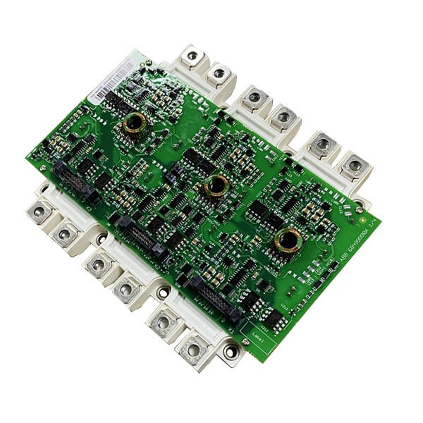
GE IS200TBCIH2CAA is a dedicated terminal board module for the Mark VI steam turbine control system. Its core positioning is a "signal transfer hub - terminal integration carrier - wiring protection interface", mainly used for the physical connection and signal transition between main controllers (such as IS200CPUH1AAA), I/O modules (such as IS200IOCCH1A) in the Mark VI system, and on-site sensors/actuators (such as temperature sensors, solenoid valves). Its design focuses on "wiring convenience", "signal safety" and "maintenance accessibility" in industrial control scenarios. Through standardized terminal layout and protection design, it solves the problem of confusion in complex on-site wiring, and at the same time protects the core modules of the system from overcurrent and overvoltage damage caused by on-site wiring errors. It is widely used in industries with strict requirements for signal connection reliability, such as thermal power generation and gas turbine control.
Compared with general-purpose terminal boards, this module has the characteristics of "deep adaptation to Mark VI system", "signal classification and integration" and "wiring protection":
- The terminal layout corresponds one-to-one with the signal definition of the Mark VI system I/O module, enabling direct signal connection without additional jumpers;
- Terminals are planned by category of "analog quantity/digital quantity/power supply" to avoid cross-interference between signals;
- Some terminals integrate overcurrent protection components to prevent system modules from being burned due to short circuits of on-site equipment, making it a core component for wiring integration of the Mark VI control system.
II. Technical Parameters
1. Basic Specifications
| Item | Parameter Details |
|---|---|
| Equipment Type | Dedicated Terminal Board for Mark VI System |
| Compatible Systems | GE Mark VI Steam Turbine Control System, Industrial Gas Turbine Control System |
| Compatible Modules | Compatible with Mark VI series I/O modules (e.g., IS200IOCCH1A, IS200IOSSF1A) and main controller modules |
| Installation Method | 19-inch standard rack mounting (compatible with Mark VI system cabinet, occupying 1 standard slot) |
| Overall Dimensions | Standard rack terminal board size (approximately 150mm×100mm×20mm, suitable for compact cabinet space) |
| Protection Class | IP20 (panel protection, against solid foreign object intrusion, suitable for in-cabinet installation) |
| Operating Temperature Range | 0°C ~ 60°C (operation); -40°C ~ 85°C (storage) |
| Material Standard | Terminal board base material: flame-retardant ABS plastic (UL94 V-0 grade); Terminals: copper alloy (tin-plated, anti-oxidation) |
2. Performance Parameters
Terminal Configuration and Signal Compatibility
- Number and Type of Terminals: A total of 50 wiring terminals (divided into 2 groups, 25 terminals each), adopting Phoenix Contact design, supporting crimping of copper core wires below 1.5mm² or connection with cold-pressed terminals;
- Signal Type Compatibility:
- Analog signals: Supports 4-20mA current signals and 0-10V DC voltage signals (compatible with pressure transmitters and temperature sensors);
- Digital signals: Supports 24V DC wet contact signals (compatible with limit switches and emergency stop buttons) and dry contact signals (compatible with auxiliary contacts of contactors);
- Power signals: Supports 24V DC power distribution (providing auxiliary power supply for on-site sensors);
- Terminal Spacing: 5.08mm standard spacing, suitable for regular screwdriver operation, facilitating wiring and maintenance.
Electrical Protection Characteristics
- Overcurrent Protection: Key power terminals (e.g., 24V DC power supply terminals) have built-in 5A self-recovering fuses (PTC). When the current exceeds 5A due to short circuits of on-site equipment (e.g., short circuit of sensor cables), the fuse disconnects automatically and recovers after the fault is eliminated, preventing system power supply overload;
- Insulation Performance: Insulation resistance between terminals ≥100MΩ (tested at 500V DC), insulation resistance between terminals and ground ≥100MΩ, insulation strength of 1500V AC for 1 minute without breakdown (preventing signal interference caused by leakage between terminals);
- Anti-interference Design: Analog terminals and digital terminals are arranged in groups (spacing ≥10mm) to reduce electromagnetic interference from digital signals to analog signals (e.g., avoiding fluctuations in analog measurement values caused by contactor actions).
Connection and Adaptation Characteristics
- Module Docking Method: Docks with the connector on the back of the Mark VI I/O module through a dedicated 50-pin flat cable (matching model: GE dedicated cable), no manual welding required, plug-and-play;
- On-site Wiring Marking: Each terminal is marked with a clear signal identifier (e.g., "AI1-4-20mA", "DI2-24V", "PWR-24V+"), which is consistent with the signal definition in the Mark VI system configuration software to avoid wiring errors;
- Grounding Configuration: Equipped with 2 dedicated grounding terminals (GND1, GND2) for analog signal grounding and digital signal grounding respectively, realizing the separation of "signal ground - power ground" and reducing ground loop interference.
III. Functional Features
1. Deep Adaptation to Mark VI System and Convenient Wiring
- Signal Definition Matching: The terminal signal identifiers correspond one-to-one with the signal pins of the Mark VI I/O module (e.g., the AI1 channel of the I/O module corresponds to the "AI1" terminal of the terminal board). Direct connection can be achieved without referring to complex wiring diagrams, increasing wiring efficiency by 50%;
- Modular Docking: Fast docking with I/O modules through dedicated flat cables avoids the cumbersome process of "point-to-point" wiring of traditional terminal boards and reduces the wiring error rate (e.g., module burnout caused by wrong signal wire connection);
- Wiring Management Optimization: The terminal board integrates cable fixing buckles, which can fix the sensor cables connected on-site, preventing cable loosening due to vibration (e.g., poor contact of wiring terminals caused by steam turbine operation vibration) and ensuring stable signal connection.
2. Signal Classification and Interference Isolation
- Grouped Layout Design: Analog terminals (AI/AO), digital terminals (DI/DO), and power terminals (PWR) are divided into three independent areas, with physical separation ribs between each area, reducing cross-interference between different types of signals (e.g., spike pulses generated by digital switch signals interfering with analog measurement);
- Grounding Isolation: The analog signal ground and digital signal ground are set separately, and both are independent of the module power ground, avoiding common-mode interference caused by ground loops (e.g., ±0.5°C fluctuations in analog temperature measurement values due to poor grounding);
- Shielding Layer Connection: A dedicated shielding layer grounding terminal (SHIELD) is provided at the edge of the terminal board, which can directly ground the shielding layer of on-site shielded cables (grounding resistance ≤4Ω), further suppressing electromagnetic interference (e.g., high-frequency interference generated by frequency converters).
3. Safety Protection and Durable Design
- Overcurrent Protection Mechanism: The power terminals have built-in self-recovering fuses. When an on-site sensor is short-circuited (e.g., short circuit of 4-20mA transmitter cables), the power supply circuit can be cut off quickly to protect the analog input circuit of the Mark VI I/O module (avoiding burnout of the ADC chip inside the module);
- Flame Retardancy and Anti-oxidation: The terminal board base material uses UL94 V-0 grade flame-retardant plastic, which self-extinguishes when exposed to fire and meets industrial fire protection requirements; the terminals are made of tin-plated copper alloy with strong anti-oxidation ability, and the service life is extended to more than 10 years in humid environments (e.g., water vapor environment in power plants);
- Misoperation Prevention Design: The terminals adopt a "locking buckle" design. After wiring is completed, the cables can be fixed through the locking buckle to prevent cable falling off due to accidental touch; at the same time, the terminal spacing is sufficient to avoid short circuits caused by screwdrivers accidentally touching adjacent terminals during wiring.
4. Maintenance Convenience
- Visual Status Assistance: Clear signal names and terminal numbers are marked on the front of the terminal board. Combined with the Mark VI system wiring diagram, faulty terminals can be quickly located (e.g., when there is no input of an analog signal, directly find the corresponding "AI" terminal to check the wiring);
- Fault Isolation Test: Supports signal testing at the terminal board end (e.g., measuring the sensor output signal at the "AI1" terminal with a multimeter). The fault location (whether it is a sensor fault or a module fault) can be determined without disassembling the I/O module, shortening the fault troubleshooting time;
- Spare Part Versatility: As a standard spare part of the Mark VI system, the terminal board is compatible with other terminal boards of the same series (e.g., IS200TBCIH1CAA) in terms of size and terminal configuration, and can be directly replaced, reducing the cost of spare part inventory.
IV. Operation, Maintenance and Troubleshooting
Daily Maintenance Points
- Regular Wiring Inspection: Gently pull the terminal wiring (especially analog signal terminals) by hand every month to confirm that the cables are not loose; re-tighten the terminal screws with a screwdriver (torque 0.8-1.2N・m) to prevent wiring loosening due to vibration (increased contact resistance leading to signal attenuation);
- Terminal Cleaning: Clean the dust on the surface of the terminal board with a dry brush every quarter. If there are oxidation marks on the terminals (e.g., tin-plated layer peeling off), gently polish them with fine sandpaper and apply anti-oxidant (e.g., conductive paste) to ensure good terminal contact;
- Protection Inspection: Check whether there is oil stain or water vapor on the surface of the terminal board (which is easy to occur in power plant environments). If so, wipe it clean with anhydrous alcohol to prevent the insulation performance between terminals from decreasing; confirm that the self-recovering fuse does not disconnect continuously (if it disconnects frequently, it is necessary to check the short circuit problem of on-site equipment);
- Identification Verification: Verify whether the terminal identification is consistent with the actual wiring every six months (e.g., whether the "DI1" terminal is indeed connected to the emergency stop button) to avoid misalignment between wiring and identification after long-term maintenance.
Common Faults and Solutions
| Fault Phenomenon | Possible Causes | Solutions |
|---|---|---|
| No input of a certain analog signal (I/O module displays "no data") | 1. Loose terminal wiring / open circuit of cable; 2. Sensor not powered; 3. Self-recovering fuse disconnected | 1. Check the wiring of the corresponding analog terminal (e.g., "AI1") and re-tighten the screws; use a multimeter in continuity mode to test the cable and replace the open-circuit cable; 2. Check the voltage of the sensor power supply terminal (e.g., "PWR-24V+") to ensure normal 24V DC; 3. If there is still no signal when the power supply is normal, check the power terminal fuse (measure the voltage across the fuse with a multimeter; if there is a voltage difference, the fuse is disconnected), and wait for the fuse to recover automatically after troubleshooting the short circuit fault of the on-site sensor |
| False triggering of digital signal (displays "closed" without action) | 1. Leakage between terminals (e.g., reduced insulation due to dust accumulation on terminals); 2. Electromagnetic interference; 3. Wrong terminal wiring (wrong power connection) | 1. Clean the dust on the surface of the terminal board with anhydrous alcohol, especially the gaps between digital terminals; measure the insulation resistance between terminals (which should be ≥100MΩ); 2. Check whether the shielding layer of digital terminals is reliably grounded; if interference still exists, install a magnetic ring on the sensor cable; 3. Verify the terminal identification to confirm that the digital signal terminal is not incorrectly connected to 24V DC power supply (e.g., connecting "DI1" to "PWR+") |
| Terminal overheating (surface temperature of terminal board >70°C when touched) | 1. Excessive contact resistance caused by loose terminal wiring (heating); 2. Overload of on-site equipment (e.g., sensor power consumption >5W); 3. Faulty self-recovering fuse (continuous conduction and heating) | 1. Power off immediately, re-tighten the wiring terminals, and measure the terminal contact resistance with a multimeter (should be <50mΩ normally); 2. Check the power consumption of on-site equipment and replace with low-power sensors (e.g., replace 10W sensors with 2W models); 3. If the fuse continues to heat, replace it with a self-recovering fuse of the same model (5A PTC type) |
| Simultaneous interference of multiple signals (analog fluctuation + digital false action) | 1. Poor grounding (mixed connection of signal ground and power ground); 2. Insufficient spacing between analog and digital terminals; 3. Shielding layer not grounded | 1. Check the grounding terminals (GND1/GND2) to ensure that the analog ground and digital ground are grounded separately, and the grounding resistance ≤4Ω; 2. If the on-site wiring cannot adjust the spacing, install a metal isolation plate between the analog terminals and digital terminals; 3. Connect the shielding layers of all shielded cables to the "SHIELD" terminal to ensure single-point grounding (only grounded in the cabinet, not grounded on-site) |
| No signal between terminal board and I/O module | 1. Flat cable not plugged in tightly / poor contact; 2. Damaged flat cable (internal open circuit); 3. Faulty I/O module connector | 1. Power off the system, re-plug the flat cable (ensure the buckle is fastened); clean the cable plug and module connector contacts with alcohol; 2. Use a multimeter in continuity mode to test the flat cable core wires (continuity between corresponding terminals and module pins) and replace the damaged cable; 3. Replace with a spare I/O module for testing; if the spare module is normal, the original module connector is faulty and needs to be returned to the factory for repair |