Description
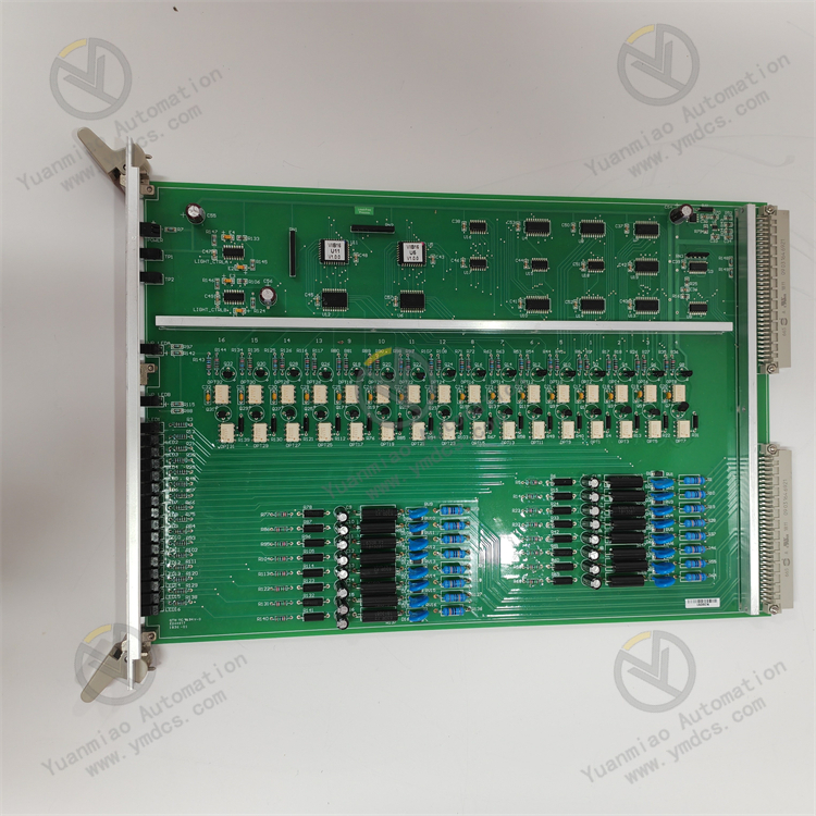
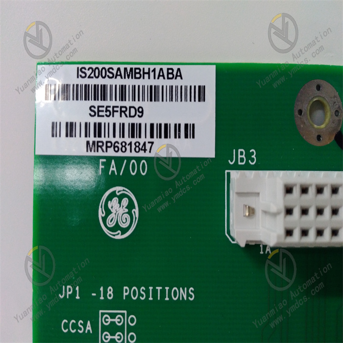
GE IS200SAMBH1ABA
1. Overview
2. Technical Specifications
2.1 Core Signal Processing Parameters
Signal Input (AI/AO/DI/DO) Configuration
- Analog Input (AI): 8 differential analog input channels, each channel can be independently configured with signal types. It supports 4-20mA DC (input impedance: 250Ω), 0-10V DC (input impedance: 100kΩ), thermocouples (Types K/J/T/R, measurement range: -270℃ to +1760℃), and RTDs (PT100/PT1000, 3-wire system, measurement range: -200℃ to +850℃).
- Analog Output (AO): 4 analog output channels, with output signals of 4-20mA DC (load ≤ 600Ω) and 0-10V DC (load ≥ 10kΩ), and output accuracy of ±0.1% F.S.
- Digital Input (DI): 16 digital input channels, supporting 24V DC dry contact/wet contact signals. The high level is ≥ 18V DC, the low level is ≤ 5V DC, and the response time is ≤ 1ms.
- Digital Output (DO): 8 digital output channels, adopting relay output (rating: 250V AC/5A, 30V DC/5A), and supporting normally open/normally closed contact configuration.
Signal Processing Accuracy and Performance
- Analog Acquisition Accuracy: For 4-20mA/0-10V signals: ±0.05% F.S.; for thermocouples: ±0.1℃ (at 25℃); for RTDs: ±0.05℃ (within 0℃ to +200℃). The sampling rate is 1kHz per channel (configurable).
- Linearity: The linearity of analog input/output is ≤ ±0.02% F.S., ensuring distortion-free signal conversion.
- Signal Isolation: Three-level electrical isolation (input-output-power supply) with isolation voltage ≥ 2500Vrms for 1 minute, common-mode rejection ratio (CMRR) ≥ 80dB (at 50Hz), and differential-mode rejection ratio (DMRR) ≥ 60dB. It effectively blocks electromagnetic interference in gas turbine sites (e.g., noise generated by generators and high-voltage cables).
2.2 Physical and Environmental Parameters
Physical Specifications
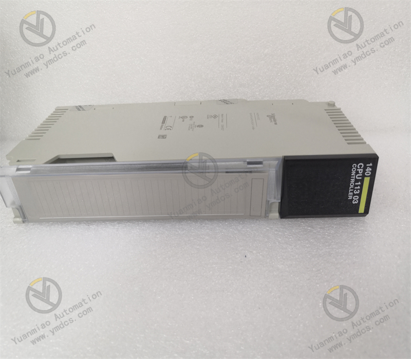
- Dimensions: 220mm (length) × 160mm (width) × 80mm (height) (including mounting clips). It adopts the standard rack slot design of the GE Mark VIe system, which can be directly inserted into the I/O rack of the Mark VIe control cabinet. It is dimensionally compatible with modules of the same series (e.g., IS200TBAIH1BAA), simplifying cabinet layout.
- Weight: Approximately 1.2kg. The modular design facilitates installation and replacement, allowing a single person to complete module insertion and removal.
Environmental Adaptability
- Operating Temperature: -40℃ to +70℃, meeting the operational requirements of high-temperature gas turbine rooms (room temperature up to 50℃ in summer) and outdoor control cabinets in cold regions (down to -30℃ in winter). No preheating is required for low-temperature startup (at -40℃), and the startup time is ≤ 30s.
- Humidity: 5% to 95% (non-condensing, complying with IEC 60068-2-3 standard), preventing component damage due to moisture in the high-humidity environment of coastal power plants.
- Protection Rating: IP20 (for installation inside control cabinets), compatible with the overall protection system of Mark VIe control cabinets (cabinet protection rating: IP54).
- Vibration and Shock Resistance: Vibration resistance rating: 10g (10Hz to 2000Hz, complying with IEC 60068-2-6); shock resistance rating: 20g (11ms pulse, complying with IEC 60068-2-27). It can withstand vibration and shock during gas turbine operation.
- Altitude: ≤ 2000m (for rated performance). When exceeding 2000m, the analog acquisition accuracy decreases by ≤ 0.02% F.S. for every 1000m increase in altitude.
2.3 Power Supply and Reliability Parameters
- Power Supply Requirements: Operating voltage: 24V DC (wide-range adaptation: 18V DC to 36V DC), powered by the backplane of the Mark VIe system rack. The operating current is ≤ 500mA (at full load), and the power consumption is ≤ 12W.
- Reliability Indicators: Mean Time Between Failures (MTBF) ≥ 300,000 hours (per Telcordia SR-332 standard at 25℃); design life ≥ 20 years. Key components (e.g., isolation chips, sampling resistors) are selected from military-grade products, meeting the "continuous operation and low maintenance" requirements of gas turbine units.
- Communication Interface: Communicates with the Mark VIe controller (e.g., IC698CPE330) via the system backplane bus, with a data transmission rate of 100Mbps and latency ≤ 1ms. It supports parameter configuration and fault diagnosis through GE's dedicated ControlST configuration software.
3. Functional Features
3.1 Compatibility with Multi-Type Signals and Accurate Processing
- Full Signal Type Adaptation: The 8 AI channels can process different types of signals simultaneously, adapting to the complex monitoring needs of gas turbines. For example, in the control of gas turbines in combined cycle power plants, the module collects signals through AI channels: K-type thermocouples (gas turbine turbine exhaust temperature: +600℃ to +1200℃), PT100 (bearing temperature: 0℃ to +150℃), 4-20mA pressure transmitters (combustion chamber pressure: 0 to 3MPa), and 0-10V speed sensors (rotor speed: 0 to 3000rpm). No additional signal converters are required, simplifying the system architecture and reducing integration costs.
High-Precision Parameter Acquisition: It adopts a 16-bit Δ-Σ ADC chip (sampling rate: 1kHz) and a low-temperature-drift (≤ 5ppm/℃) reference voltage source to ensure accurate collection of key parameters. For instance, when collecting the gas turbine bearing temperature (target value: 80℃), the measurement error can be controlled within ±0.05℃, enabling early detection of slight overheating of the bearing (e.g., 80.1℃) and avoiding bearing burnout due to poor lubrication (with a single maintenance cost exceeding 500,000 RMB).
Optimized Interference Suppression: The three-level electrical isolation and high CMRR design can effectively resist strong electromagnetic interference on gas turbine sites. Near generators (electromagnetic interference intensity: 10V/m), the fluctuation of the 4-20mA pressure signal collected by the module is reduced from ±0.5mA to ±0.02mA, ensuring the combustion chamber pressure control accuracy (±0.01MPa) and avoiding power fluctuations caused by unstable combustion of the gas turbine.
3.2 Dedicated Adaptation for Gas Turbine Control
- Coordination of Startup and Load Adjustment: It collaborates deeply with the Mark VIe controller to participate in the gas turbine startup sequence and load adjustment. During the startup phase, the module receives commands from the controller, controls the fuel valve actuator (via 4-20mA signal) through the AO channel, and gradually increases fuel supply (from 10% to 40% opening). At the same time, it collects signals from the speed sensor (via the DI channel) and feeds back a "startup ready" signal to the controller when the speed reaches 2800rpm (startup speed). During the load adjustment phase, it adjusts the opening of the guide vane actuator (via the AO channel) according to the grid load demand (received through system communication), realizing smooth adjustment of the unit power from 30% to 100% of the rated value, with an adjustment response time ≤ 100ms.
Safety Protection Signal Transfer: As a key part of the gas turbine safety protection system, the module collects emergency shutdown signals (via DI channels) such as "overspeed protection (rotational speed ≥ 3300rpm)", "overtemperature protection (turbine exhaust temperature ≥ 1250℃)", and "low lubricating oil pressure (≤ 0.1MPa)". It transmits the signals to the controller within 1ms, and the controller issues a shutdown command. The module triggers the fuel valve closure and emergency shutdown solenoid valve action via the DO channel. The response time from fault occurrence to unit shutdown is ≤ 500ms, avoiding major equipment damage.
Integration of Condition Monitoring Data: It integrates more than 20 operating parameters collected (such as "bearing temperature", "vibration value", and "fuel pressure") into the historical database of the Mark VIe controller via the system bus. It supports trend analysis (e.g., monthly trend of bearing temperature) and fault diagnosis (e.g., sudden increase in vibration value warning of rotor unbalance) through the ControlST software, providing data support for the preventive maintenance of gas turbines and extending the unit's overhaul cycle (from 1.5 years to 2 years).
3.3 Industrial-Grade Reliability and Fault-Tolerant Design
- Durability in Extreme Environments: The internal circuit board is coated with nano-level three-proof paint (moisture-proof, salt spray-proof, and mildew-proof), ensuring no component corrosion after 5 years of continuous operation in the high-temperature and high-oil-pollution environment of gas turbine rooms. The housing is made of magnesium-aluminum alloy (lightweight and good heat dissipation). Even when the module operating temperature reaches 70℃, the internal component temperature is still controlled within 85℃ (lower than the component's rated temperature of 125℃).
Fault Self-Diagnosis and Redundancy: It supports channel-level fault diagnosis and can identify 12 types of faults such as "AI channel disconnection", "AO channel short circuit", and "power supply abnormality". Fault codes (e.g., "E03 = Thermocouple disconnection in AI2 channel") are displayed on the system HMI, and the fault occurrence time and signal values before the fault are recorded, facilitating maintenance personnel to quickly locate problems. It supports dual-module hot redundancy configuration (main and standby modules operate synchronously). When the main module fails, the standby module switches automatically within 10ms, ensuring uninterrupted gas turbine control and complying with the IEC 61508 SIL 2 safety level requirements.
Low-Maintenance Design: It adopts a "fan-less and wear-part-free" design to avoid poor heat dissipation caused by fan failure. The terminals are made of gold-plated material (plating thickness ≥ 10μm) with a plug-in life of ≥ 1000 times, ensuring no poor contact during long-term use. The average maintenance interval is ≥ 5 years, significantly reducing the maintenance workload and costs of gas turbine units.
3.4 Convenient Configuration and Maintenance
- ControlST Configuration Compatibility: Module parameters can be configured intuitively through the GE ControlST configuration software without coding. By selecting the "IS200SAMBH1ABA" module model in the software, users can configure the signal type of each channel (e.g., "AI1 = K-type thermocouple", "DI1 = dry contact signal") and alarm thresholds (e.g., "Alarm when bearing temperature ≥ 90℃") in a graphical manner. After configuration, the parameters are downloaded to the module via Ethernet, with a configuration time ≤ 30 minutes.
Online Parameter Modification and Calibration: It supports online modification of channel parameters (e.g., alarm thresholds, sampling rates) without shutdown. It also supports single-channel online calibration (inputting standard signals such as 4mA/20mA, and the module automatically corrects deviations) with a calibration accuracy of ±0.01% F.S. The calibration process does not affect the normal operation of other channels, avoiding unit shutdown caused by calibration (with a single shutdown loss exceeding 100,000 RMB).
- Remote Maintenance Support: Through the remote communication interface of the Mark VIe system (e.g., Ethernet), remote condition monitoring (e.g., channel signal values, fault status) and parameter configuration of the module can be realized. Maintenance personnel can complete daily inspections and parameter adjustments of the module without going to the site (especially suitable for remote power plants), improving maintenance efficiency by 60%.
4. Operation Guide
4.1 Installation Process
Preparation for Installation
- Module Inspection: After unpacking, check that the module has no deformation in appearance, no damage to interfaces, the label model (IS200SAMBH1ABA) is consistent with the order, and accessories (mounting clips, terminal blocks) are complete.
- Tools and Materials: Prepare a Phillips screwdriver (PH2), torque wrench (5-10N・m), wire crimping tool, insulation tester (2500V), and insulating gloves.
- Installation Environment: Reserve a module installation slot in the Mark VIe control cabinet. Ensure the slot matches the module pins (to avoid incorrect insertion). The cabinet should be well-ventilated, with a heat dissipation space of ≥ 50mm reserved around the module.
Installation Steps
- Rack Preparation: Open the Mark VIe control cabinet, confirm that the power supply of the I/O rack is disconnected, and clean the pins in the rack slot (free of dust and oxidation).
- Module Insertion: Align the module with the rack slot (note that the positioning protrusion on the module matches the positioning groove of the slot), push it in slowly until a "click" sound is heard (indicating the mounting clip is locked), and gently shake the module to confirm it is not loose.
- Wiring Operation (to be performed by certified high-voltage electricians with power off):
- Signal Wiring: Connect AI/AO signal cables (shielded twisted-pair cables) to the terminal block on the front of the module. Pay attention to the positive and negative polarity of thermocouple signals (red for positive, black for negative). For RTD signals, distinguish the 3-wire connection (power supply, signal, common wire). Connect DI/DO signal cables to the corresponding terminals. Dry contact signals require an external 24V DC power supply.
- Grounding Wiring: Connect the "PE" terminal of the module to the protective ground of the control cabinet (grounding resistance ≤ 4Ω) using a 6mm² copper core cable. The shielding layer of the signal cable should be grounded at one end (on the module side).
- Insulation Test: Use a 2500V insulation tester to measure the insulation resistance between input-output, input-ground, and output-ground of the module. A value ≥ 100MΩ is considered qualified. After confirming no short circuit, close the control cabinet door.
4.2 Configuration and Debugging
Configuration (ControlST Software)
- Project Creation: Open the ControlST software, create a new project (select "Mark VIe" as the system type), add the "IS200SAMBH1ABA" module (select the corresponding model from the hardware library), and assign a slot number for the module in the rack (e.g., Slot 3).
- Channel Configuration: Double-click the module icon to enter the channel configuration interface, and set parameters for each AI/AO/DI/DO channel. For AI channels: select the signal type (e.g., "AI1 = K-type thermocouple"), measurement range (0~1200℃), and alarm threshold (alarm at 1200℃). For AO channels: set the output signal type (4-20mA) and corresponding actuator (e.g., "AO1 = fuel valve actuator"). For DI/DO channels: set the signal type (dry contact/wet contact, normally open/normally closed).
- Configuration Download: Download the configured project to the Mark VIe controller via Ethernet. The controller automatically synchronizes the parameters to the module. After the download is completed, restart the module to make the parameters take effect.