Description
GE IS200DTAOH1ABA
I. Overview
GE IS200DTAOH1ABA is an industrial-grade high-density digital output module in the Mark VIe series control system, specifically designed for the execution of discrete control signals in industrial-grade steam turbines, gas turbines, and combined cycle units. As the "core of control command execution" in the Mark VIe system, it undertakes the key responsibilities of converting logical commands issued by the control module (such as valve start-stop, motor control, alarm triggering, and interlock protection) into switch signals recognizable by on-site equipment, as well as implementing signal isolation, power driving, status feedback, and fault diagnosis. It serves as a hardware bridge connecting the control layer and the on-site execution layer, ensuring the accurate implementation of control commands. It is widely used in industrial scenarios with strict requirements for digital output reliability, anti-interference capability, and environmental adaptability, such as power generation, petrochemicals, metallurgy, and energy industries.
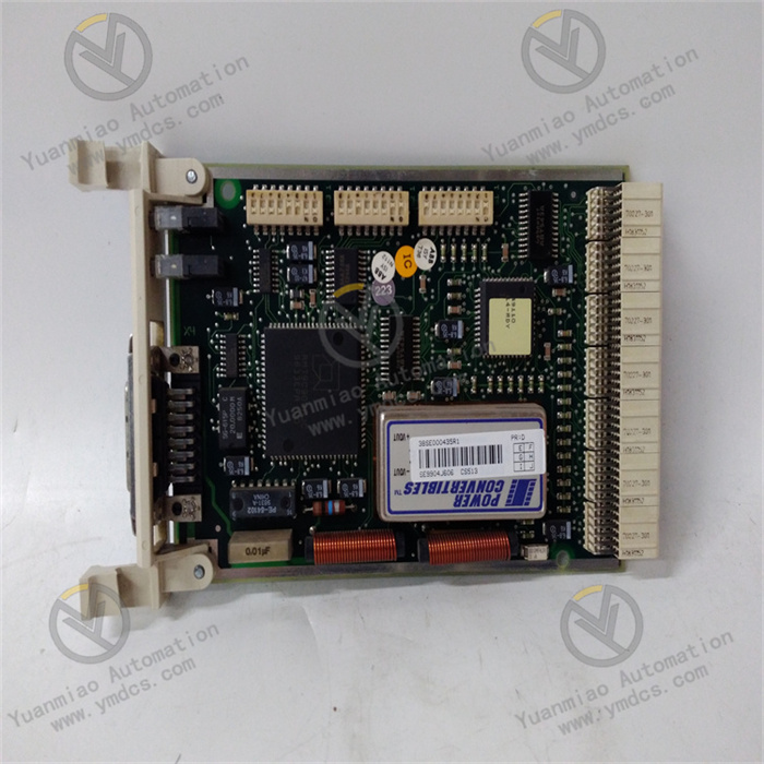
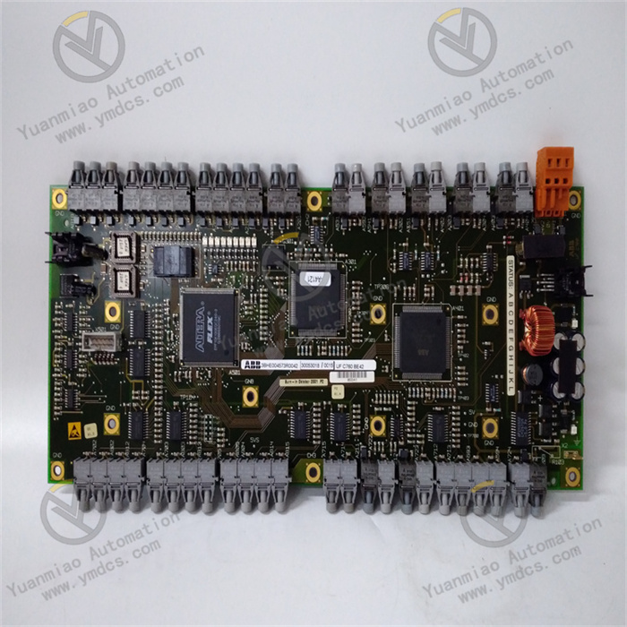
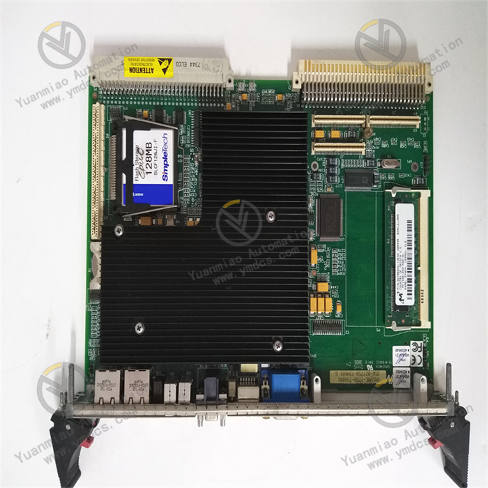
The module adopts a standard 3U VME industrial board form factor (approximately 100mm in height, 233mm in width, and 23mm in thickness) and has no independent operation panel. It realizes high-speed data interaction and stable power supply with the control module and power module through the system backplane. The surface of the module adopts an industrial-grade anti-interference layout; key power devices (such as sealed relays and high-voltage-resistant MOSFETs) are equipped with metal shields and efficient heat sinks. The pin soldering process complies with the IPC-A-610 Class 3 industrial standard, enabling it to withstand long-term high-load operation and complex electromagnetic environments (such as high-voltage motor start-stop and high-frequency frequency converter interference). At the same time, it has wide-temperature, moisture-proof, and salt-fog-resistant characteristics, allowing stable operation in industrial sites with high interference, wide temperature differences, and high humidity, thus ensuring the continuity of digital output signals and the safety of equipment driving.
II. Technical Parameters
1. Signal Output and Driving Parameters
| Parameter Category | Specific Specifications |
|---|---|
| Output Channel Configuration | 16 independent digital output channels, supporting group configuration of relay output/transistor output (8 channels per group, independently configurable) |
| Output Signal Type | Relay output: dry contact, normally open/normally closed mode configurable via software; Transistor output: wet contact, NPN/PNP polarity switchable via software |
| Output Voltage Range | Relay output: compatible with 24V DC, 48V DC, 110V AC, 220V AC loads; Transistor output: 24V DC±10% |
| Output Current Capacity | Relay output: maximum single-channel resistive load current 4A, inductive load current 1.5A (power factor 0.7); Transistor output: maximum single-channel continuous current 1.5A, peak current 5A (duration ≤ 100ms) |
| Response Time | Relay output: pull-in time ≤ 15ms, release time ≤ 8ms; Transistor output: turn-on/turn-off time ≤ 100μs |
| Signal Isolation | Isolation voltage between channels ≥ 2kVrms, isolation voltage between output and backplane ≥ 2.5kVrms, isolation voltage between input and output ≥ 2.5kVrms, blocking common-mode interference and ground loops |
| Status Feedback | Each channel has a built-in current detection resistor (accuracy ±3%), supporting output status (on/off), load current monitoring and overload detection, feedback update frequency ≥ 8Hz |
2. Electrical and Environmental Parameters
- Power Supply Requirements: Digital circuit power supply +5V DC (allowable fluctuation ±5%), drive circuit power supply ±12V DC (allowable fluctuation ±5%), relay coil power supply +24V DC (allowable fluctuation ±10%); Maximum power consumption ≤ 20W (when all channels are relay outputs at full load), adopting "natural heat dissipation + local air cooling" hybrid heat dissipation (micro fan integrated in the relay area), full-load operating temperature ≤ 55℃;
- Operating Temperature: -25℃~65℃ (wide-temperature design), suitable for low-temperature outdoor control cabinets, high-temperature industrial workshops (such as steel plants, oil refineries) and other scenarios;
- Storage Temperature: -40℃~85℃, no risk of component aging or pin corrosion during long-term storage;
- Relative Humidity: 5%~95% (non-condensing), the board surface is coated with a moisture-proof and salt-fog-resistant coating with a thickness of ≥0.1mm, which can operate in coastal high-salt-fog environments (5% salt fog concentration, no corrosion after 72 hours of continuous spraying);
- Anti-interference Performance: Complies with IEC 61000-6-2 industrial anti-interference standards, electrostatic discharge (ESD) protection ±2kV (contact discharge)/±4kV (air discharge), electrical fast transient pulse group (EFT) protection ±1kV (power port)/±0.5kV (signal port), radio frequency radiation immunity ≥15V/m (80-1000MHz);
- Surge Protection: The output port is equipped with ±5kV (1.2/50μs) surge protection (complies with IEC 61000-4-5 standard) to prevent damage to the module caused by reverse electromotive force when inductive loads are powered off.
3. Physical and Interface Parameters
- Dimensions: 3U VME board type (100mm×233mm×23mm), compatible with standard 19-inch industrial control cabinet installation, supporting hot swapping (requires Mark VIe system authorization);
- Weight: Approximately 1.0kg (including relays, heat sinks and shields);
- Output Interface: 16 Phoenix terminal interfaces (each channel corresponds to 1 output terminal + 1 common terminal + 1 feedback terminal). The terminals are made of anti-corrosion material, supporting screw-fastened wiring. Conductor specifications: relay output 0.5-2.5mm², transistor output 0.5-1.5mm², with anti-misinsertion design (clear terminal identification);
- Indicator Lights: The front panel of the board is equipped with 6 main LED indicators (PWR: power status, green; RUN: operating status, green; ERR: fault status, red; COMM: communication status, yellow; GRP1/GRP2: channel group status, green). GRP1/GRP2 lights are always on indicating that the corresponding 8 channels are normal, and flashing indicates overload/short circuit in the group; each channel is equipped with 2 micro LED lights (OUT: output on, on; FB: feedback normal, on), providing intuitive feedback of single-channel status.
4. Communication and Diagnostic Parameters
- Communication Interface: 1 VME64x backplane interface, data transmission rate with control module up to 40MB/s, supporting interrupt requests (triggered when output is overloaded or short-circuited, response time ≤100ms);
- Diagnostic Functions: Supports channel short-circuit detection (response time ≤150ms), overload detection (triggered when current exceeds 120% of rated value), relay sticking detection (alarm when command and feedback are inconsistent for 100ms), drive chip fault detection. Fault information includes channel number and type (such as "GRP1 CH5 short circuit"), uploaded to the monitoring system through the backplane;
- Configuration Method: Supports remote configuration via GE ToolboxST software, including channel type (relay/transistor), output mode, overload threshold (1.1-1.5 times rated current). Configuration parameters are saved when power is off (built-in 64KB EEPROM), supporting configuration file backup.
III. Functional Features
1. Multi-type Output Adaptation, Meeting Diverse Load Requirements
- Flexible Configuration of 16-channel Groups: 16 channels are divided into groups of 8 channels each, supporting mixed configuration of relays and transistors (such as GRP1 driving 220V AC motor contactors, GRP2 driving 24V DC solenoid valves). It can adapt to different types of loads without additional modules, saving 35% of cabinet space compared with single-type modules, suitable for actuator-intensive scenarios such as steam turbine valve control and boiler auxiliary machine start-stop;
- Wide Voltage and Current Coverage: Relay output is compatible with AC and DC multi-voltage loads (24V DC-220V AC), 4A current can drive small and medium-sized motor contactors (such as 1.5kW motors); Transistor output 1.5A continuous current is suitable for high-frequency action loads (such as solenoid valve commutation, response frequency ≥1kHz), meeting the driving needs of loads with different powers and action frequencies;
- Reliable Action Guarantee: Relays adopt industrial-grade sealed models (MTBF ≥500,000 operations), with contacts resistant to arc corrosion, adapting to frequent start-stop scenarios (such as 50 start-stops per day, service life exceeding 8 years); Transistor output ≤100μs response time, achieving high-frequency control (such as gas turbine fuel valve regulation).
2. Full-link Protection, Improving Operational Reliability
- Dual Isolation Design: 2kVrms isolation between channels and 2.5kVrms isolation between output and backplane, combined with independent power supply, block common-mode interference (such as 500V common-mode voltage of frequency converter) and ground loop in industrial field, avoiding channel crosstalk; Photoelectric isolation between power circuit and digital circuit prevents reverse influence of load interference on control layer, with signal transmission accuracy reaching 99.99%;
- Multi-level Load Protection: Each channel has built-in overcurrent protection (self-recovering fuse for relay channel, current-limiting resistor for transistor channel). When the load is short-circuited or overloaded (such as motor stall), the output is cut off within 150ms to protect the module and load; The output port has ±5kV surge protection to absorb reverse electromotive force when inductive load is powered off (such as 200V pulse when motor is powered off), avoiding damage to drive chips;
- Closed-loop Feedback Control: Each channel integrates current detection and status feedback, forming a "command-output-feedback" closed loop: after issuing a "valve closing" command, the load action is confirmed through feedback current (such as 0.5A normal current of solenoid valve). If there is no feedback, an alarm is issued immediately to avoid misjudgment of "command issued but load not acting", ensuring unit safety (such as emergency shutdown of steam turbine).
3. Intelligent Diagnosis and Convenient Operation and Maintenance
- Software-based Parameter Configuration: Adjust channel parameters remotely through GE ToolboxST software (such as relay/transistor switching, overload threshold setting) without on-site hardware modification, taking effect within 5 seconds; Configuration files can be backed up to PC and directly imported during batch deployment of modules of the same model, improving operation and maintenance efficiency by 50%;
- Accurate Fault Location: Fault information is fed back through both LED and monitoring system (such as GRP1 light flashing + ERR light on, monitoring display "GRP1 CH3 overload"), allowing maintenance personnel to quickly locate faulty channels and loads without checking one by one; Relay sticking detection warns of faults in advance to avoid load misoperation (such as valve misclosing);
- Status Visualization: Each channel has "OUT/FB" dual LED design, allowing on-site personnel to judge the status without software (such as "OUT" on and "FB" off = load open circuit); The monitoring system can view output current and relay action times in real time, providing data for preventive maintenance (such as replacement recommended when actions reach 400,000 times).
4. Industrial-grade High-reliability Design, Adapting to Harsh Environments
- Wide Temperature and Environmental Resistance: Operating at -25℃~65℃ wide temperature range, relay pull-in time ≤18ms at -25℃, transistor output stable at 65℃; Moisture-proof and salt-fog-resistant coating and anti-corrosion terminals adapt to coastal high-humidity and high-salt-fog environments, avoiding component corrosion;
- Mechanical and Electrical Durability: Complies with IEC 60068-2-6 vibration protection (10-500Hz, 5g acceleration) and IEC 60068-2-27 impact protection (50g acceleration, 11ms pulse), withstanding transportation and on-site vibration impact to prevent component loosening; Key components have long service life (relay action ≥500,000 times, transistor life ≥100,000 hours), reducing replacement frequency;
- Efficient Heat Dissipation: A micro fan (rotating speed 2500rpm, noise ≤40dB) is integrated in the relay area, combined with aluminum heat sink, reducing relay temperature by 15℃ (when all channels are on); Transistor channel patch heat dissipation ensures chip temperature ≤60℃ when 1.5A continuous output, ensuring long-term stability.