Description
GE IS200AEPCH1BAA
I. Overview
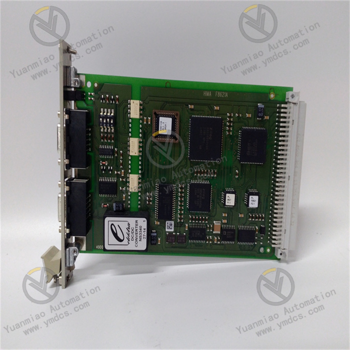
The GE IS200AEPCH1BAA is a high-density digital input module in the Mark VIe series control system, specifically designed for the acquisition of discrete signals from industrial-grade steam turbines, gas turbines, and combined cycle units. Serving as the "digital signal entry point" of the Mark VIe system, it undertakes the critical responsibilities of isolating, level-converting, and status-monitoring discrete signals from on-site equipment (such as valve status, switch positions, and fault contact signals). It acts as a core bridge connecting on-site actuators, sensors, and control modules, ensuring that control modules can obtain the on-off status of equipment in a real-time and reliable manner. It is widely used in industrial scenarios with strict requirements for digital signal acquisition response speed and anti-interference capability, such as power generation, petrochemicals, and metallurgy.
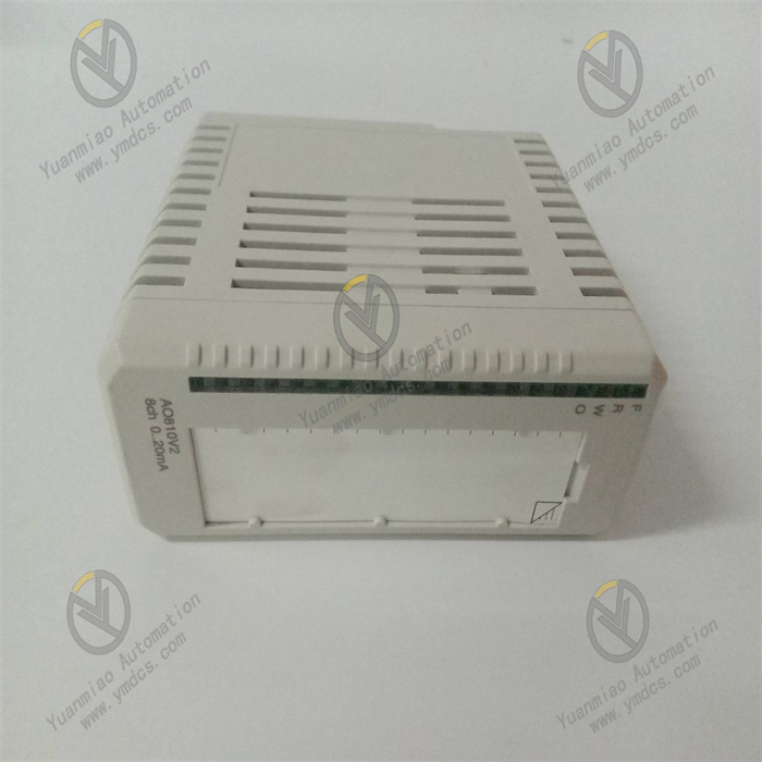
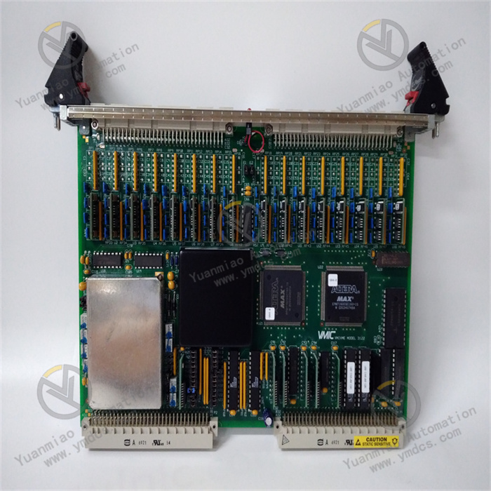
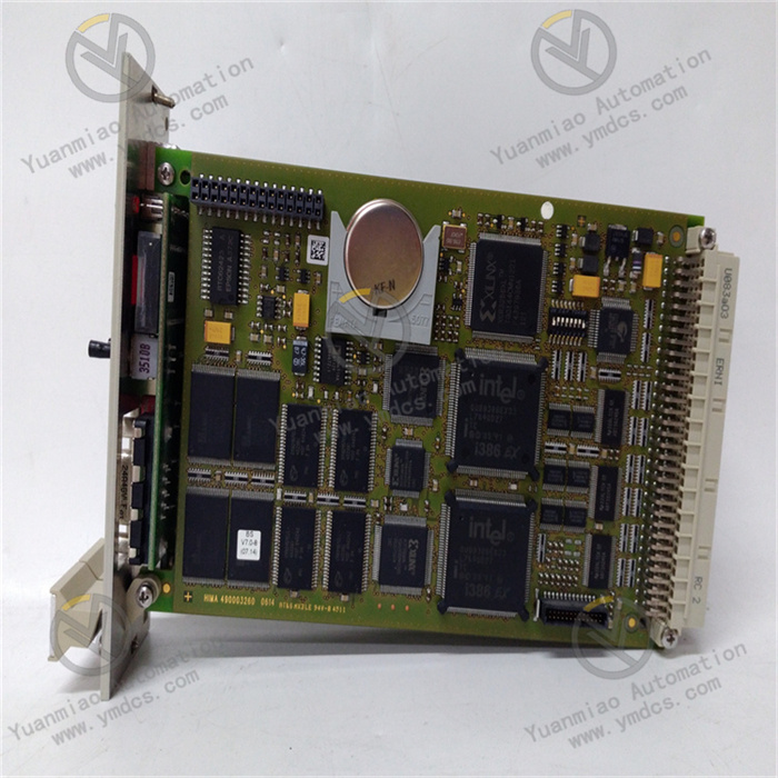
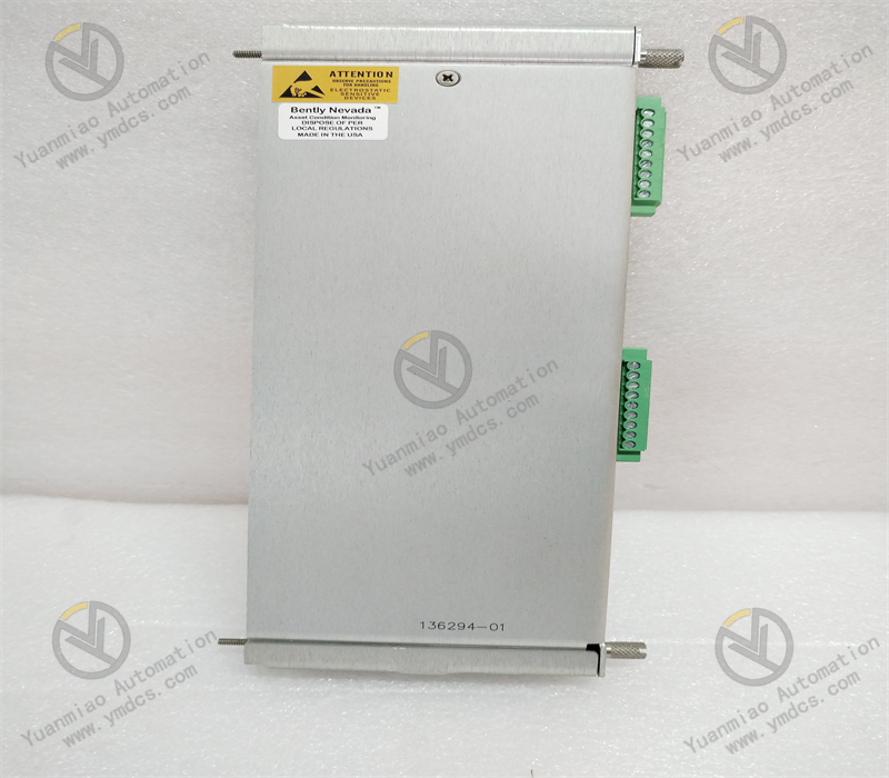
This module adopts a standard 3U VME industrial board form factor (approximately 100mm in height, 233mm in width, and 22mm in thickness) and has no independent operation panel. It realizes data interaction and power supply with control modules and power modules through the system backplane. The surface of the module features an industrial-grade anti-interference layout; key signal isolation chips (such as optocouplers) are equipped with metal shields, and the pin soldering process complies with the IPC-A-610 Class 3 industrial standard. It can withstand long-term high-load operation and complex electromagnetic environments (such as motor start-stop and high-frequency interference from frequency converters), ensuring the stability and accuracy of digital signal acquisition and adapting to harsh operating conditions in industrial sites, including high interference, wide temperature differences, and high humidity.
II. Technical Specifications
1. Signal Acquisition and Processing Specifications
| Specification Category | Specific Specifications |
|---|---|
| Input Channel Configuration | 32 differential digital input channels, supporting dry contact/wet contact switching (configurable in groups of 16 channels) |
| Supported Signal Types | Dry contact signals (passive contacts, requiring external 24V DC power supply); Wet contact signals (active signals, 24V DC/48V DC) |
| Input Voltage Range | Dry contact: External power supply 24V DC±10%; Wet contact: 24V DC/48V DC±10% |
| Input Current | Dry contact: On-state current 5-10mA (to ensure reliable contact closure); Wet contact: Input current ≤ 5mA |
| Response Time | Signal rising edge/falling edge response time ≤ 1ms, ensuring rapid capture of equipment status changes (e.g., valve emergency stop signals) |
| Signal Isolation | Isolation voltage between channels ≥ 1kVrms, isolation voltage between input and backplane ≥ 2.5kVrms, blocking common-mode interference and ground loops |
| Contact Bounce Filtering | Built-in hardware debounce circuit (configurable debounce time: 1-10ms), software debounce algorithm (adjustable debounce window: 1-20ms) |
2. Electrical and Environmental Specifications
- Power Supply Requirements: Input voltage is +5V DC (for digital circuits) and +24V DC (for isolation circuits), with an allowable voltage fluctuation range of ±5%; maximum power consumption ≤ 12W, adopting natural cooling design (aluminum heat sinks integrated on the board surface), operating temperature ≤ 55℃;
- Operating Temperature: -25℃~65℃ (wide-temperature design), suitable for extreme scenarios such as high-temperature workshops, outdoor control cabinets, and frigid regions;
- Storage Temperature: -40℃~85℃, no risk of component aging or pin corrosion during long-term storage;
- Relative Humidity: 5%~95% (non-condensing), the board surface is coated with a moisture-proof insulating coating (thickness ≥ 0.1mm), usable in coastal high-salt-fog environments (salt fog concentration of 5%);
- Anti-Interference Performance: Complies with the IEC 61000-6-2 industrial anti-interference standard; ESD (Electrostatic Discharge) protection: ±2kV (contact discharge)/±4kV (air discharge); EFT (Electrical Fast Transient) protection: ±1kV (power port)/±0.5kV (signal port); RF (Radio Frequency) radiation immunity ≥ 10V/m (80-1000MHz);
3. Physical and Interface Specifications
- Dimensions: 3U VME board form factor (100mm×233mm×22mm), compatible with standard 19-inch industrial control cabinet installation, supporting hot-swapping (requires Mark VIe system authorization);
- Weight: Approximately 0.7kg (excluding accessories);
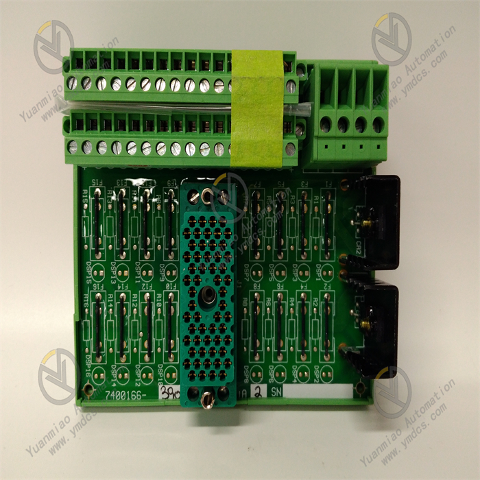
- Input Interface: 32 Phoenix terminal interfaces (each channel corresponds to 1 signal input + 1 common terminal), supporting screw-fastened wiring, wire specification of 0.5-2.5mm², with anti-misinsertion design (clear terminal polarity marking);
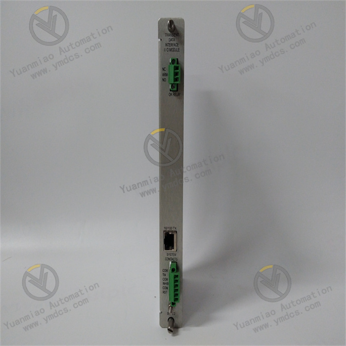
- Indicator Lights: The front panel of the board is equipped with 6 LED indicators (PWR: Power status, green; RUN: Operation status, green; ERR: Fault status, red; COMM: Communication status, yellow; GRP1-GRP2: Channel group status, green). The GRP1-GRP2 lights being steadily on indicates that the corresponding 16 channels are normal, while blinking indicates an abnormality in the group (e.g., contact sticking). Each channel has a corresponding micro LED light (located next to the terminal): the light being on indicates the signal is "on", and off indicates "off", providing intuitive feedback on the single-channel status.
4. Communication and Diagnosis Specifications
- Communication Interface: 1 VME64x backplane interface, data transmission rate with control modules up to 40MB/s, supporting interrupt requests (e.g., triggering interrupts when signal status changes abruptly);
- Diagnostic Functions: Supports channel open/short circuit detection, contact sticking detection, and power fault detection; fault response time ≤ 100ms, fault information (including faulty channel number and fault type) is uploaded to the monitoring system via the backplane bus;
- Configuration Method: Supports remote configuration of channel type (dry contact/wet contact), debounce time, and interrupt trigger conditions (e.g., rising edge trigger/falling edge trigger) via GE ToolboxST software; configuration parameters are retained after power-off.
III. Functional Features
1. High-Density Multi-Type Digital Signal Acquisition
- Efficient Integration of 32 Channels: The 32 differential input channels adopt a "dual-group design" (16 channels per group), supporting mixed acquisition of dry contacts and wet contacts. No additional modules are required, significantly saving cabinet space (reducing space occupation by 50% compared to 16-channel modules). It is particularly suitable for industrial scenarios with dense sensors (such as centralized acquisition of steam turbine valve status, motor start-stop contacts, and fault alarm signals);
- Wide Voltage Adaptation: Dry contacts support external 24V DC power supply, and wet contacts are compatible with two common industrial voltages (24V DC/48V DC). It can adapt to different on-site equipment (such as 24V DC solenoid valve contacts and 48V DC motor fault contacts) without replacing the module, reducing spare parts inventory costs;
- Rapid Response: With a signal response time of ≤ 1ms, it can capture transient signals such as equipment emergency stops and faults in real time (e.g., contact changes caused by sudden valve closure), avoiding control logic misjudgment due to response delays and ensuring the safe operation of units (e.g., rapid acquisition of steam turbine emergency shutdown signals).
2. Full-Link Anti-Interference and Signal Fidelity
- Multi-Level Isolation Protection: 1kVrms isolation between channels and 2.5kVrms isolation between input and backplane block common-mode interference (such as 500V common-mode voltage generated by frequency converters) and ground loops commonly found in industrial sites, avoiding signal crosstalk between different channels. The input circuit uses optocouplers (e.g., TLP181) for signal isolation, ensuring digital signals are free from noise pollution, with a signal transmission accuracy of 99.999%;
- Hardware + Software Dual Debouncing: At the hardware level, each channel is connected in series with an RC debounce circuit (debounce time 1-10ms selectable via jumpers) to effectively suppress contact bounce (e.g., bouncing when relay contacts close). At the software level, a sliding window debounce algorithm (adjustable debounce window 1-20ms) is used to further filter spike pulse interference, ensuring stable acquired signal status (e.g., avoiding "frequent on-off" false alarms caused by contact bounce);
- Polarity Self-Adaptation: Wet contact signals support positive and negative polarity self-adaptation (e.g., when the positive and negative poles of a 24V DC signal are reversed, the module automatically identifies and collects the signal normally). There is no need to check polarity on-site, simplifying wiring operations and reducing the wiring error rate of maintenance personnel.
3. Flexible Configuration and Intelligent Diagnosis
- Software-Based Parameter Configuration: Via GE ToolboxST software, the signal type (dry contact/wet contact), debounce time (hardware 1-10ms/software 1-20ms), and interrupt trigger conditions (e.g., rising edge trigger for "fault alarm", falling edge trigger for "fault recovery") of each channel can be configured remotely. No on-site adjustment of hardware jumpers is required, adapting to the signal characteristics of different on-site equipment (e.g., slow contacts require long debounce time, fast contacts require short debounce time). It supports backup and restoration of configuration files, enabling rapid batch deployment of modules of the same model and reducing operation and maintenance costs;
- Channel-Level Fault Diagnosis: Built-in comprehensive fault diagnosis function, real-time monitoring of channel open circuits (e.g., dry contact wire breakage), short circuits (e.g., wet contact signal short circuit), contact sticking (e.g., relay contacts unable to open), and power faults (e.g., lack of external power supply for dry contacts). Fault information is fed back through both LED indicators and the monitoring system (e.g., blinking ERR light + "GRP1 CH5 Short Circuit" displayed on the monitoring interface), allowing maintenance personnel to quickly locate faulty channels without checking on-site equipment one by one;
- Status Visualization: Each channel is equipped with an independent micro LED light, allowing maintenance personnel to intuitively judge the signal status ("on"/"off") through the light's "on"/"off" state. Combined with the GRP1-GRP2 group status lights, it can quickly distinguish between "single-channel faults" and "group faults", simplifying the on-site fault troubleshooting process (e.g., judging whether a certain valve contact is normal without connecting software).
4. Industrial-Grade High-Reliability Design
- Wide-Temperature and Moisture-Proof Protection: With a wide operating temperature range of -25℃~65℃ and a moisture-proof, salt-fog-resistant coating, it can operate long-term in high-temperature workshops (e.g., steel plants) and coastal high-humidity environments. It avoids component performance degradation caused by low temperatures (e.g., reduced response speed of optocouplers) and pin corrosion caused by high humidity;
- Mechanical and Electrical Protection: Complies with the IEC 60068-2-6 standard for vibration protection (10-500Hz, 5g acceleration) and the IEC 60068-2-27 standard for shock protection (50g acceleration, 11ms pulse). It can withstand vibration and shock during equipment transportation and operation, avoiding interface loosening and component damage. The ports are equipped with ±2kV surge protection to prevent channel damage caused by lightning strikes or power grid fluctuations;
- Long-Term Stability: Key components (such as optocouplers and debounce capacitors) use industrial-grade long-life devices (MTBF ≥ 100,000 hours), and the pin soldering process complies with the IPC-A-610 Class 3 standard. After long-term operation (5 years), the channel on/off judgment error is ≤ 0.5V, reducing the need for frequent calibration and replacement and lowering the total lifecycle cost.