Description
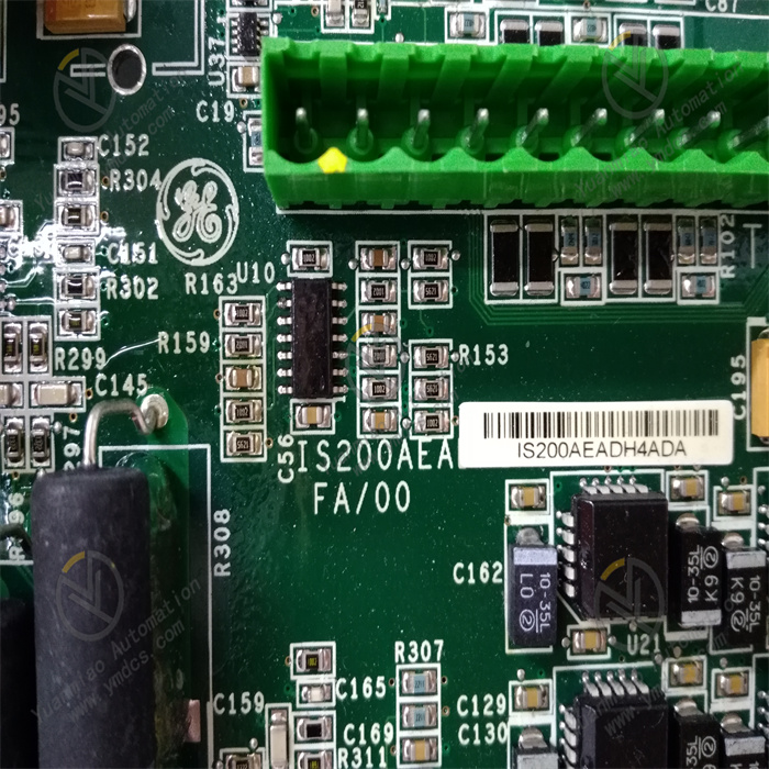
GE IS200AEADH4ADA
I. Overview
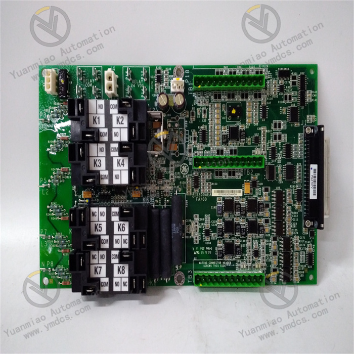
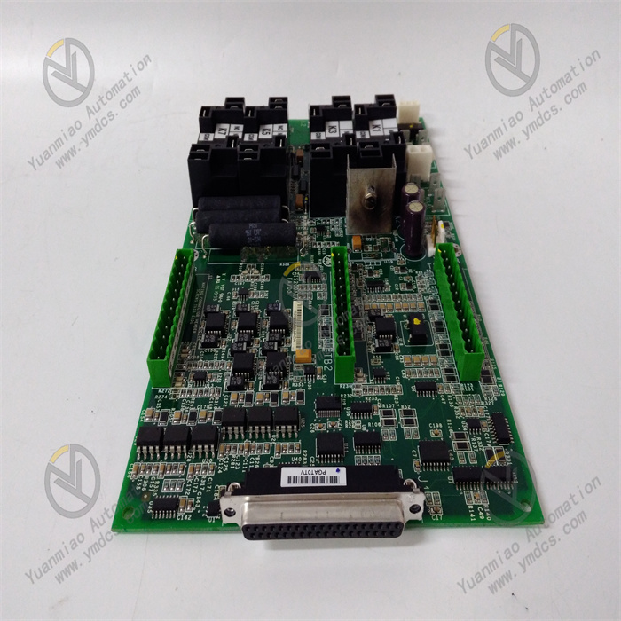
The GE IS200AEADH4ADA is a high-density analog input module in the Mark VIe series control system, specifically designed for the precise acquisition of analog signals from industrial-grade steam turbines, gas turbines, and combined cycle units. As the "signal acquisition front-end" of the Mark VIe system, it undertakes the critical responsibility of isolating, amplifying, filtering, and digitizing analog signals output by on-site sensors (such as pressure, temperature, and flow signals). Serving as a core bridge connecting on-site equipment and control modules, it ensures that control modules receive high-fidelity, low-latency raw data. It is widely used in industrial scenarios with strict requirements for signal acquisition accuracy and anti-interference capability, such as power generation, petrochemicals, and metallurgy.
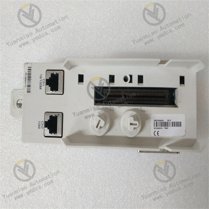
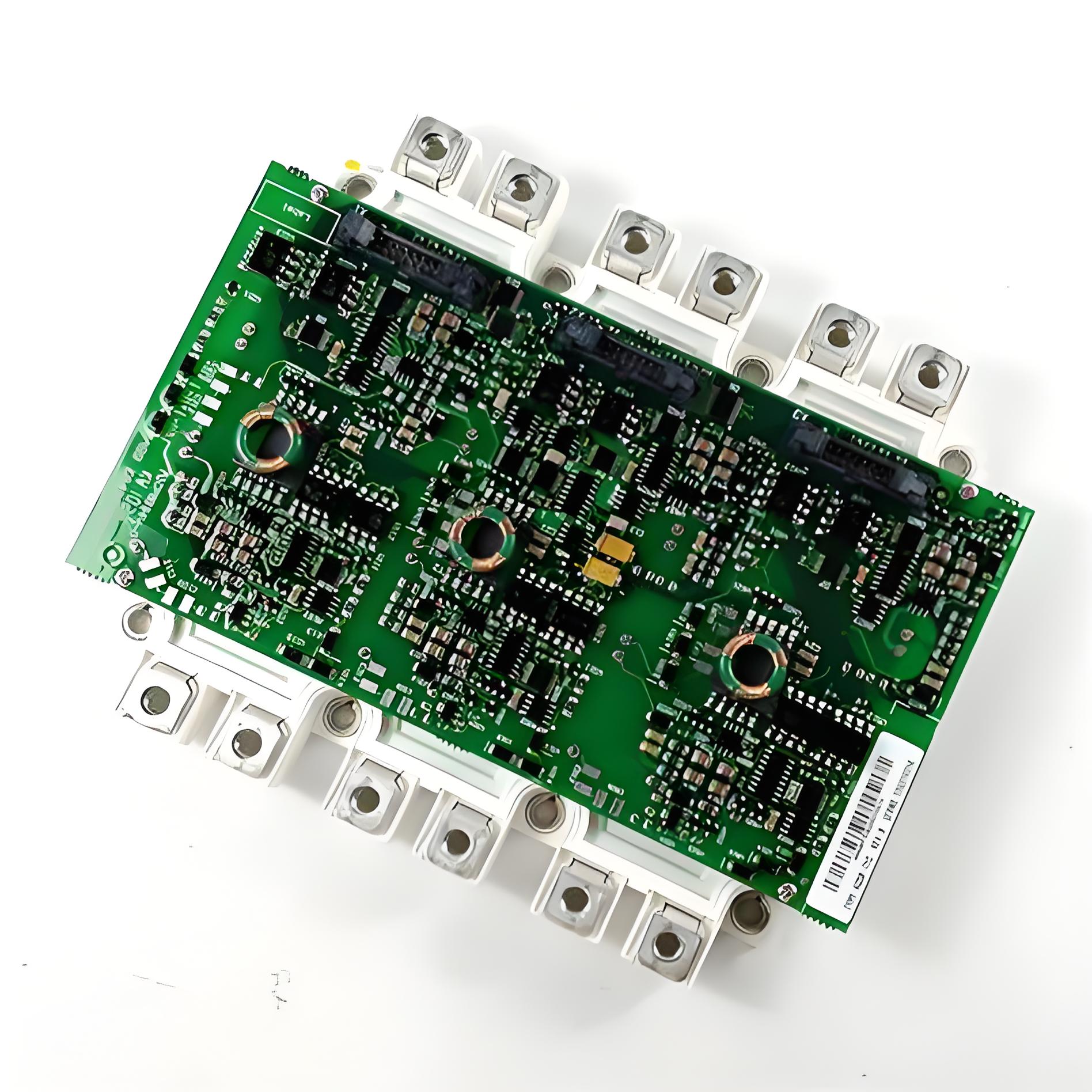
This module adopts a standard 3U VME industrial board form factor (approximately 100mm in height, 233mm in width, and 22mm in thickness) and has no independent operation panel. It realizes data interaction and power supply with control modules and power modules through the system backplane. The surface of the module features an industrial-grade anti-interference layout; key signal conditioning chips (such as instrumentation amplifiers and high-precision ADCs) are equipped with metal shields, and the pin soldering process complies with the IPC-A-610 Class 3 industrial standard. It can withstand long-term high-load operation and complex electromagnetic environments (such as motor start-stop and high-frequency interference from frequency converters), ensuring the stability of signal acquisition functions and data accuracy, and adapting to harsh operating conditions in industrial sites, including high interference, wide temperature differences, and high humidity.
II. Technical Specifications
1. Signal Acquisition and Processing Specifications
| Specification Category | Specific Specifications |
|---|---|
| Input Channel Configuration | 32 differential analog input channels, supporting single-ended/differential switching (configurable in groups of 8 channels) |
| Supported Signal Types | Standard industrial signals: 4-20mA, 0-10V, 0-5V; Thermocouple signals: Type K, J, T; RTD signals: PT100 (3-wire) |
| Measurement Accuracy | 4-20mA/0-10V signals: ±0.05% FS; Thermocouple signals: ±0.8℃ (Type K, 0-1000℃); PT100 signals: ±0.1% FS (0-800℃) |
| Cold-Junction Compensation | Built-in cold-junction compensation circuit, compensation accuracy of ±0.3℃, compensation range of -20℃~70℃ |
| ADC Conversion Performance | 16-bit resolution, configurable sampling rate: 10Hz/20Hz/50Hz (independently adjustable per channel), conversion delay ≤ 5ms |
| Signal Isolation | Isolation voltage between channels ≥ 1kVrms, isolation voltage between input and backplane ≥ 2.5kVrms, blocking common-mode interference and ground loops |
2. Electrical and Environmental Specifications
- Power Supply Requirements: Input voltage is +5V DC (for digital circuits) and ±12V DC (for analog circuits), with an allowable voltage fluctuation range of ±5%; maximum power consumption ≤ 15W, adopting natural cooling design (aluminum heat sinks integrated on the board surface), operating temperature ≤ 55℃;
- Operating Temperature: -25℃~65℃ (wide-temperature design), suitable for extreme scenarios such as high-temperature workshops, outdoor control cabinets, and frigid regions;
- Storage Temperature: -40℃~85℃, no risk of component aging or pin corrosion during long-term storage;
- Relative Humidity: 5%~95% (non-condensing), the board surface is coated with a moisture-proof insulating coating (thickness ≥ 0.1mm), usable in coastal high-salt-fog environments (salt fog concentration of 5%);
- Anti-Interference Performance: Complies with the IEC 61000-6-2 industrial anti-interference standard; ESD protection: ±2kV (contact discharge)/±4kV (air discharge); EFT (Electrical Fast Transient) protection: ±1kV (power port)/±0.5kV (signal port); RF radiation immunity ≥ 10V/m (80-1000MHz);
3. Physical and Interface Specifications
- Dimensions: 3U VME board form factor (100mm×233mm×22mm), compatible with standard 19-inch industrial control cabinet installation, supporting hot-swapping (requires Mark VIe system authorization);
- Weight: Approximately 0.8kg (excluding accessories);
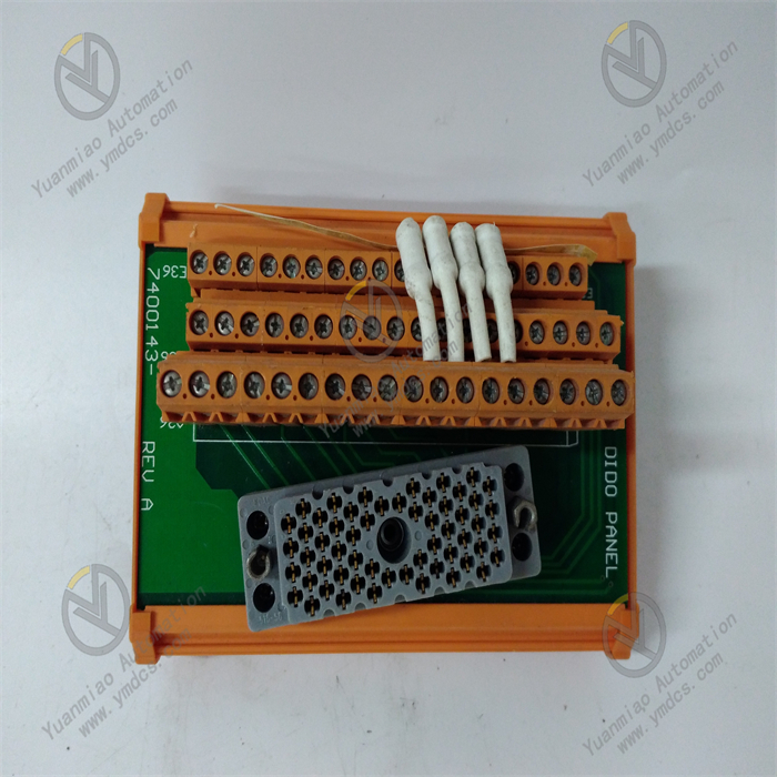
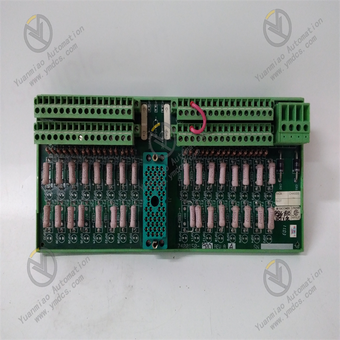
- Input Interface: 32 Phoenix terminal interfaces (each channel corresponds to 1 signal input + 1 common terminal), supporting screw-fastened wiring, wire specification of 0.5-2.5mm², with anti-misinsertion design;
- Indicator Lights: The front panel of the board is equipped with 6 LED indicators (PWR: Power status, green; RUN: Operation status, green; ERR: Fault status, red; COMM: Communication status, yellow; CH1-CH2: Channel group status, green). The CH1-CH2 lights being steadily on indicates that the corresponding 8 channels are normal, while blinking indicates an abnormality in the group (e.g., sensor open circuit).
4. Communication and Calibration Specifications
- Communication Interface: 1 VME64x backplane interface, data transmission rate with control modules up to 40MB/s, supporting interrupt requests (e.g., triggering interrupts when signals exceed the range);
- Calibration Method: Supports user-defined calibration (via GE ToolboxST software), each channel can be independently calibrated for zero point and gain, recommended calibration cycle is once a year;
- Fault Diagnosis: Supports channel open/short circuit detection, signal over-range detection, and ADC conversion fault detection; fault response time ≤ 100ms, fault information is uploaded to the monitoring system via the backplane bus.
III. Functional Features
1. High-Density Multi-Type Signal Acquisition
- Efficient Integration of 32 Channels: The 32 differential input channels adopt a "grouped design" (8 channels per group), supporting mixed acquisition of standard industrial signals, thermocouples, and RTDs. No additional modules are required, significantly saving cabinet space (reducing space occupation by 50% compared to 16-channel modules). It is particularly suitable for industrial scenarios with dense sensors (such as multi-point acquisition of steam turbine bearing temperature and boiler pressure);
- Wide Signal Range Adaptation: The 4-20mA signal supports an extended range of 0-20mA (configurable via software); thermocouple signals cover -200℃~1300℃ (Type K); PT100 signals cover -200℃~850℃. It can meet the full-scenario acquisition needs of industrial sites, from low to high temperatures and from weak to standard signals;
- High-Precision Data Acquisition: Combined with a 16-bit ADC converter and instrumentation amplifier (e.g., AD8221), it achieves precise amplification of weak signals (e.g., 4mA corresponding to 0.1MPa pressure) with an adjustable amplification factor of 10-100 times. The measurement accuracy reaches ±0.05% FS, ensuring that the acquired data truly reflects the equipment operating status (e.g., pressure fluctuations of ±0.005MPa can be accurately captured).
2. Full-Link Anti-Interference and Signal Fidelity
- Multi-Level Isolation Protection: 1kVrms isolation between channels and 2.5kVrms isolation between input and backplane block common-mode interference (such as 500V common-mode voltage generated by frequency converters) and ground loops commonly found in industrial sites, avoiding signal crosstalk between different channels. Analog and digital circuits are powered independently to prevent digital circuit noise from affecting analog signal acquisition, increasing the signal signal-to-noise ratio to over 65dB;
- Hardware + Software Dual Filtering: At the hardware level, each channel is connected in series with an RC low-pass filter circuit (cutoff frequency of 50Hz/60Hz selectable via jumpers) to effectively suppress power frequency interference. At the software level, a combined algorithm of sliding window filtering and Kalman filtering is used to eliminate spike pulse interference (such as transient signal jumps caused by motor start-stop) and random noise. The signal fluctuation amplitude after filtering is reduced to ±0.02% FS, ensuring stable and reliable data uploaded to the control module;
- Optimized Cold-Junction Compensation: For thermocouple signals, a built-in high-precision temperature sensor (accuracy ±0.1℃) monitors the module's ambient temperature in real time. Combined with software algorithms, it dynamically compensates for cold-junction errors with a compensation accuracy of ±0.3℃. Compared with traditional fixed compensation methods, the temperature measurement error is reduced by 40% (e.g., at 25℃, the measurement error of Type K thermocouples is reduced from ±1.2℃ to ±0.8℃).
3. Flexible Configuration and Intelligent Diagnosis
- Software-Based Parameter Configuration: Via the GE ToolboxST software, the signal type (e.g., changing a channel from 4-20mA to Type K thermocouple), sampling rate (10Hz/20Hz/50Hz), and filtering parameters (filter window size) of each channel can be configured remotely. No on-site adjustment of hardware jumpers is required, adapting to scenarios where different sensors are replaced (e.g., replacing a pressure sensor with a temperature sensor). It supports backup and restoration of configuration files, enabling rapid batch deployment of modules of the same model and reducing operation and maintenance costs;
- Full-Lifecycle Diagnosis: Built-in channel-level fault diagnosis function, real-time monitoring of sensor open/short circuits (e.g., thermocouple wire breakage, PT100 short circuit), signal over-range (e.g., 4-20mA signal exceeding 22mA), and ADC conversion abnormalities. Fault information is fed back through both LED indicators and the monitoring system (e.g., blinking ERR light + "CH16 Open Circuit" displayed on the monitoring interface), allowing maintenance personnel to quickly locate faulty channels without checking sensors one by one;
- Hot-Swap Maintenance: Supports hot-swapping with Mark VIe system authorization. When replacing the module, there is no need to shut down the control system; maintenance personnel only need to execute the "module offline" command in the monitoring system to safely insert or remove the module. This reduces maintenance downtime from "hour-level" to "minute-level", making it particularly suitable for non-interruptible industrial production scenarios (such as steam turbine monitoring in thermal power plants).
4. Industrial-Grade High-Reliability Design
- Wide-Temperature and Moisture-Proof Protection: With a wide operating temperature range of -25℃~65℃ and a moisture-proof, salt-fog-resistant coating, it can operate long-term in high-temperature workshops (e.g., steel plants) and coastal high-humidity environments. It avoids component performance degradation caused by low temperatures (e.g., reduced ADC conversion accuracy) and pin corrosion caused by high humidity;
- Mechanical and Electrical Protection: Complies with the IEC 60068-2-6 standard for vibration protection (10-500Hz, 5g acceleration) and the IEC 60068-2-27 standard for shock protection (50g acceleration, 11ms pulse). It can withstand vibration and shock during equipment transportation and operation, avoiding interface loosening and component damage. The ports are equipped with ±2kV surge protection to prevent channel damage caused by lightning strikes or power grid fluctuations;
- Long-Term Stability: Key components (such as ADC chips and instrumentation amplifiers) use industrial-grade long-life devices (MTBF ≥ 100,000 hours), and the pin soldering process complies with the IPC-A-610 Class 3 standard. After long-term operation (5 years), the channel drift is ≤ ±0.1% FS, reducing the need for frequent calibration and replacement and lowering the total lifecycle cost.
IV. Operation Guide
1. Installation Steps
(1) Cabinet Installation (Mark VIe System Rack)
- Prepare Tools: Phillips screwdriver, 4 M3 screws, ESD anti-static wristband (essential to prevent electrostatic damage to components);
- Anti-Static Operation: Wear the ESD anti-static wristband, ensure good grounding of the wristband (ground resistance ≤ 1MΩ), and take the module out of the anti-static packaging;
- Insert into Rack: Align the module with the 3U slot of the Mark VIe system rack, push it smoothly along the guide rails, and ensure that the gold fingers at the bottom of the module are fully in contact with the backplane. A "click" sound indicates that the module is locked in place;
- Secure the Module: Fasten the mounting holes on the side of the module to the rack uprights with M3 screws, applying a torque of 1.2N·m to avoid damaging the module housing due to over-tightening;
- Installation Check: Gently pull the module to confirm no looseness, and ensure that the front panel of the module is flush with the rack surface without inclination.
(2) Independent Test Installation (Laboratory Scenario)
- Test Platform Setup: Install the module on a VME test backplane and connect it to a dedicated test power supply (output +5V DC/±12V DC, ripple ≤ 50mV);
- Wiring Protection: Connect a 1A fuse in series between the input terminals and the test signal source to prevent channel damage due to signal overload during testing;
- Space Reservation: Reserve at least 3cm of heat dissipation space around the module, and avoid placing it adjacent to other heat-generating components (such as power modules) to ensure effective natural cooling.
2. Wiring Steps
(1) Input Signal Wiring (Taking 4-20mA Signal as an Example)
- Power-Off Confirmation: Ensure both the module power supply and the signal source are turned off to avoid component damage caused by live wiring;
- Terminal Identification: Check the module terminal labels to confirm the corresponding terminals for "CH1+" (signal positive), "CH1-" (signal negative), and "GND" (common ground);
- Wire Preparation: Select 0.5-2.5mm² multi-strand copper-core shielded wire, strip off the insulation layer (approximately 5mm), and remove the oxide layer on the wire surface (gently polish with sandpaper);
- Terminal Wiring: Insert the wire from the "+" terminal of the signal source into the "CH1+" terminal, the wire from the "-" terminal of the signal source into the "CH1-" terminal, and the common ground wire into the "GND" terminal. Tighten the terminal screws with a flat-head screwdriver (torque of 0.8N·m) to ensure the wires are secure (no displacement when gently pulled);
- Shield Grounding: Ground the outer shield mesh of the shielded wire at one end (ground resistance ≤ 4Ω), and select the signal source side as the grounding end to avoid ground loops caused by grounding at both ends.
(2) Thermocouple Signal Wiring (Taking Type K as an Example)
- Polarity Confirmation: The red wire of the Type K thermocouple is "+" and the yellow wire is "-". Check the module terminal labels to confirm the corresponding terminals for "CH9+" (thermocouple +) and "CH9-" (thermocouple -);
- Wiring Operation: Insert the red wire of the thermocouple into the "CH9+" terminal and the yellow wire into the "CH9-" terminal. No common ground connection is required (thermocouples are differential signals), then tighten the terminal screws;
- Cold-Junction Compensation Check: Ensure there is no local high temperature around the module (e.g., near the air outlet of a cooling fan) so that the cold-junction compensation sensor can accurately monitor the ambient temperature and avoid compensation errors.
3. Configuration and Maintenance Operations
(1) Initial Configuration (GE ToolboxST Software)
- Software Connection: Connect the PC to the Mark VIe system controller via Ethernet, open the ToolboxST software, and log in to the system (enter the username and password, administrator privileges required);
- Module Identification: In the "Hardware Configuration" interface of the software, the system automatically identifies the IS200AEADH4ADA module (displaying the module model and serial number). If not identified, check the backplane communication connection;
- Channel Configuration:
- Select the "CH1-CH8" channel group, set the signal type to "4-20mA", sampling rate to "20Hz", and filter window to "5";
- Select the "CH9-CH16" channel group, set the signal type to "Type K Thermocouple", and enable cold-junction compensation;
- Click "Apply Configuration" and wait for the configuration to be delivered (approximately 10s). The software will prompt "Configuration Successful".
- Calibration Operation:
- Enter the "Calibration" interface, select the "CH1" channel, connect a 4mA standard signal (output by a signal generator), and click "Zero Calibration";
- Connect a 20mA standard signal, click "Gain Calibration", and the software will automatically save the calibration parameters;
- Repeat the above steps to calibrate other channels. After calibration, check the "Calibration Report" to confirm that the error of all channels is ≤ ±0.05% FS.
(2) Daily Maintenance
- Status Monitoring: Check the module's LED indicators daily. The module is normal when the PWR light is on (normal power supply), RUN light is on (normal operation), ERR light is off (no fault), and COMM light is on (normal communication). Check the channel data via the ToolboxST software weekly, and compare it with the actual sensor output (e.g., measure the 4-20mA signal with a multimeter) to confirm that the acquired data error is within the allowable range;
- Cleaning and Maintenance: Clean dust from the module terminals and heat sinks with compressed air


