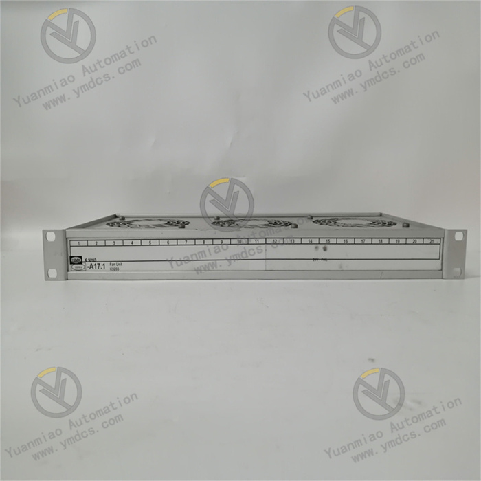


Description
1. Product Overview
Pioneer Magnetics PM3326B‑6‑1‑2‑E is a rack‑mount AC/DC front‑end power supply of PM3300 series manufactured by Pioneer Magnetics, USA. It serves as the core power module for cabinet‑based distributed power supply systems deployed in industrial automation, telecommunication base stations, medical equipment, rail transit, military and avionics applications. Designed for 19‑inch standard rack installation, the unit efficiently converts wide‑range AC mains (85‑264 V AC) into stable DC bus voltage, supplying clean, regulated DC power with overcurrent and overvoltage protection for rack‑mounted controllers, I/O modules, communication devices, sensors and auxiliary systems.
It has undergone comprehensive industrial‑grade tests including full‑load aging, temperature cycling, vibration‑shock test, dielectric withstand, EMC immunity and short‑circuit protection. Capable of 7×24‑hour non‑stop full‑load operation, it withstands harsh cabinet conditions such as high enclosed temperature, dust‑humidity environment, alternating temperature cycles, grid fluctuation and surge transients. It addresses common drawbacks of traditional linear power supplies such as low efficiency, excessive heat generation, bulky dimension, grid harmonic pollution and system downtime caused by single‑point failures. Widely adopted for new‑build industrial control system integration, retrofit replacement of legacy power modules and strategic spare‑part stock for critical racks, it delivers core hardware support for stable power supply of control systems.
2. Functional Features
2.1 High power factor and high efficiency for energy‑saving and cost reduction
Built‑in active PFC (Power Factor Correction) circuit achieves power factor above 0.99 under full‑load condition, greatly mitigating grid harmonic pollution and reactive‑power loss and complying with IEC 61000‑3‑2 harmonic‑current limits and industrial‑grid power‑quality requirements. The post‑stage LLC resonant soft‑switch topology combined with synchronous rectification delivers overall efficiency over 90 %. Compared with traditional linear and hard‑switch power supplies, heat dissipation loss is significantly reduced, easing cabinet thermal burden and lowering long‑term operating electricity costs, which meets modern industrial energy‑saving and green‑data‑center requirements.
2.2 Wide‑range AC input compatible with global power grids and harsh field conditions
The power supply accepts 85‑264 V AC wide‑range input at 47‑63 Hz, compatible with global grid voltage levels. Integrated input‑surge‑current suppression, EMI filtering, over‑/under‑voltage protection and frequency‑adaptive circuits ensure continuous and non‑rebound output under grid‑voltage fluctuation, momentary sag and spike‑surge conditions. Stable long‑term operation is guaranteed in sites with poor power quality such as power plants, petrochemical plants, metallurgical facilities and mines, preventing control‑system power loss, data corruption and unplanned unit shutdown triggered by grid disturbances.
2.3 N+1 redundant parallel capability for high‑reliability power delivery without single‑point failure
The ‑6‑1‑2‑E configuration supports multi‑module parallel N+1 redundant operation. Each power module automatically shares load current via current‑sharing bus. Upon single‑module failure, remaining modules seamlessly undertake full‑load demand with undisturbed output voltage. Combined with rack‑mount PDU (Power Distribution Unit) and redundant bus design, a power‑supply system free of single‑point‑of‑failure can be constructed for mission‑critical applications where power loss is strictly prohibited, including plant DCS/SIS, rail‑transit signaling, medical imaging and telecommunication core‑network infrastructures.
2.4 Comprehensive multi‑level protection and self‑diagnosis with visible operating status
Multiple hardware‑based protection mechanisms are implemented: over‑voltage protection (OVP), over‑current protection (OCP), short‑circuit protection (SCP), over‑temperature protection (OTP), input reverse‑polarity protection and fan‑fault protection. Front‑panel LED indicators display AC input status, DC output status, fault alarm, over‑temperature warning and fan operating condition. Telemetry parameters including output voltage, output current, internal temperature, fan speed and accumulated runtime can be uploaded to upper‑level monitoring systems via communication interfaces such as RS‑485 / PMBus, enabling remote status supervision and predictive maintenance.
2.5 Low‑ripple low‑noise output for stable operation of sensitive electronics
Multi‑stage LC filtering and post‑stage LDO (Low‑Dropout) regulation circuits suppress DC output ripple and noise to millivolt level. It provides clean power for power‑sensitive devices such as high‑precision PLC/DCS controllers, analog acquisition modules, eddy‑current preamplifiers and weak‑signal sensors, avoiding measurement drift, data bit‑error and false‑logic triggering induced by power‑supply ripple and crosstalk. It serves as an ideal power‑supply solution for precision industrial measurement and control systems.
2.6 Standard rack‑mount plug‑in design for convenient maintenance and replacement
Adopting 19‑inch standard rack‑mount modular plug‑in architecture, the module features precise rack alignment, easy assembly and secure latching. Hot‑swap replacement is supported without power‑off, rewiring or system shutdown. Uniform mechanical dimensions and interface definitions ensure compatibility with other PM3300‑series power supplies and interoperability with mainstream third‑party rack‑mount power units of identical form factor. It greatly cuts troubleshooting time and spare‑part varieties for critical racks, suiting non‑stop‑operation maintenance scenarios in industrial sites.
3. Technical Specifications
3.1 Core Compatibility Parameters
| Item | Specification |
|---|---|
| Full Part Number | PM3326B‑6‑1‑2‑E |
| Brand | Pioneer Magnetics (USA, professional industrial power‑supply vendor) |
| Product Series | PM3300 series high‑power‑factor rack‑mount switching power supply |
| Product Type | AC/DC front‑end power‑supply module |
| Installation | 19‑inch standard rack plug‑in mounting, hot‑swap supported |
| Redundancy | N+1 multi‑module parallel redundancy with automatic current sharing |
| Applicable Systems | Industrial DCS/SIS control cabinets, PLC systems, telecommunication base stations, rail‑transit signaling and medical‑equipment rack power supply |
| Core Functions | AC‑DC conversion, PFC power‑factor correction, regulated output, N+1 redundant current sharing, multi‑level protection, status monitoring and communication telemetry |
| Typical Applications | Redundant power supply for plant DCS/SIS, petrochemical control systems, rail‑transit signaling power, distributed DC bus for industrial control cabinets |
3.2 Electrical Performance Parameters
| Item | Specification |
|---|---|
| Input Voltage | 85‑264 V AC wide‑range, 47‑63 Hz, auto‑adaptable to global grids |
| Input Power Factor | Active PFC correction, PF≥0.99 at full load, low harmonic current |
| Overall Efficiency | Typical full‑load efficiency ≥90 %, LLC resonant soft‑switch plus synchronous rectification |
| Output Voltage / Current | Standard DC bus voltage (e.g. 24 V / 48 V) defined by ‑6 grade; rated output current and power as marked on nameplate |
| Regulation Accuracy | Load regulation and line regulation better than industrial standards; output ripple at millivolt level |
| Protection | OVP, OCP, SCP, OTP, input‑surge suppression, reverse‑polarity protection |
| Redundancy & Current Sharing | N+1 parallel automatic current sharing; faulty module exits without disturbance; load undertaken by remaining units |
| Status Indication | Front‑panel LEDs for AC OK, DC OK, fault, temperature and fan status; remote‑communication telemetry available |
3.3 Environmental & Physical Parameters
| Item | Specification |
|---|---|
| Operating Temperature | Industrial wide‑range for enclosed‑cabinet high‑temperature conditions (typical ‑10 ℃ ~ +70 ℃ with derating) |
| Storage Temperature | Suitable for extreme ambient conditions during storage and transportation |
| Humidity | 5 %‑95 % RH, non‑condensing; tolerant to dusty‑humid cabinet environments |
| Cooling Scheme | Intelligent temperature‑controlled forced‑air cooling; fan speed auto‑adjusted with temperature, low noise |
| Environmental Resistance | Dust‑proof, moisture‑resistant, vibration‑shock resistant, surge‑withstand, high‑EMI immunity |
| Installation | 19‑inch standard rack hot‑swap plug‑in installation with locking handle and anti‑misinsertion structure |
| Mechanical Construction | Metal chassis, flame‑retardant PCB, aluminum heat‑dissipation housing, anti‑loosening, vibration‑resistant and anti‑aging |
4. Hardware Configuration & Structural Advantages
4.1 Core Hardware Configuration
PM3326B‑6‑1‑2‑E adopts high‑power‑density rack‑mount power‑supply hardware architecture of Pioneer Magnetics PM3300 series. Key assemblies include input EMI‑filter and surge‑suppression circuit, active‑PFC boost stage, LLC resonant half‑bridge conversion stage, synchronous‑rectification output stage, multi‑stage LC output filter, intelligent fan temperature‑control unit, auxiliary power supply, control‑protection IC, current‑sharing parallel circuit and status‑indication loop. The front‑end PFC circuit rectifies AC input and generates stable high‑voltage DC bus with power factor approaching 1. The rear‑end LLC resonant topology implements ZVS (Zero‑Voltage Switching) to reduce switching loss and EMI. Synchronous rectification utilizes low‑Rds(on) MOSFETs instead of conventional Schottky diodes to improve high‑current output efficiency.
Gold‑plated high‑current contacts are adopted on rear‑side rack‑backplane AC‑input and DC‑output connectors to guarantee stable contact resistance without overheating under heavy‑current conditions. The metal front panel accommodates status LEDs, locking handle and maintenance interface. Low‑profile rack form factor and high‑density component mounting cooperate with aluminum heat sink and intelligent temperature‑controlled fan to deliver high‑power output within compact rack space. Critical components pass strict OEM screening including full‑load aging, thermal cycling, vibration and EMC tests, optimized for long‑term cabinet‑operation scenarios with continuous running, grid fluctuation and high enclosed temperature.
4.2 Structural & Engineering Advantages
The 19‑inch standard hot‑swap modular form factor shares uniform dimensions with other PM3300‑series units. Multiple modules can be mounted in one rack to realize N+1 redundancy. The front‑panel locking handle enables tool‑free extraction and replacement without disconnection of rack main circuit. DC outputs are paralleled to rack DC bus via backplane connectors; AC input is fed through rack‑backplane terminals or front‑panel wiring terminals. Modular design shortens power‑supply replacement time from hours (conventional cabinet‑integrated power sources) to minutes, drastically mitigating downtime risk for critical control systems.
High standardization and good spare‑part interoperability allow physical interchange with mainstream third‑party front‑end power supplies of identical form factor, such as Bel Power, Astec and Lambda. Cooperated with rack‑mount power‑monitoring units (SNMP / PMBus monitoring cards), operators can remotely monitor output voltage, current, internal temperature, fan speed and accumulated runtime of each power module from control rooms. Incipient risks including fan aging, output drift and temperature rise can be identified in advance for predictive maintenance. It constitutes core hardware for power‑supply architecture of modern high‑reliability industrial control systems.
5. Working Principle
PM3326B‑6‑1‑2‑E switching power supply implements multi‑stage AC‑DC conversion workflow: AC input → EMI filtering & surge suppression → rectification & PFC power‑factor correction → LLC resonant isolated step‑down → synchronous rectification → multi‑stage filtering & voltage regulation → status monitoring & protection, converting mains power into stable and clean DC bus voltage efficiently.
During operation, AC mains is fed into the power‑supply via rack‑mounted AC input terminals. Input EMI filter suppresses conducted interference and surge current before AC is rectified into pulsating DC. The subsequent active‑PFC boost circuit adopts high‑frequency switching control to stabilize high‑voltage DC bus around 400 V DC, meanwhile forcing input current waveform to follow input‑voltage waveform for near‑unity power factor and low harmonic current.
High‑voltage DC bus is delivered to LLC resonant half‑bridge converter, where high‑frequency transformer accomplishes galvanic isolation and voltage step‑down. Operating under resonant condition, the LLC circuit enables ZVS for main switching devices with minimal switching loss and low EMI. High‑frequency AC on transformer secondary is rectified into low‑voltage DC by synchronous‑rectification MOSFETs. Output LC filter eliminates high‑frequency ripple and generates regulated DC output (e.g. 24 V / 48 V), which is fed to rack DC bus through backplane connectors to power various control‑system modules.
Control loops sample output voltage and current in real‑time, comparing against reference values to adjust duty cycles of PFC and LLC switches for voltage regulation and current limitation. In case of output overload, short‑circuit, over‑voltage, over‑temperature or fan failure, protection circuits activate immediately to cut off output or trigger derating, meanwhile illuminating front‑panel fault LED and reporting alarm via communication port. Under N+1 redundant configuration, multiple power modules share load current automatically via current‑sharing bus. Faulty modules exit operation automatically while remaining modules take over the load seamlessly with zero disturbance on output voltage.
6. Troubleshooting
6.1 Front‑panel AC‑OK LED off or no output
| Probable Cause | Inspection Method | Remedial Action |
|---|---|---|
| No AC input, tripped circuit‑breaker or loose input terminals | Measure AC input terminal voltage to verify 85‑264 V AC range | Check upstream AC circuit‑breakers and contactors; fasten input terminals; restore power supply |
| Blown input surge‑suppression component or fuse | Inspect fuse appearance; measure input‑side resistance | Replace fuse and surge‑absorption component with identical ratings; investigate root‑cause of external short‑circuit |
| Damaged internal auxiliary power supply or main conversion circuit | AC input voltage normal but AC‑OK indicator remains off | Perform hot‑swap replacement with spare PM3326B unit per procedure; return defective unit for factory repair |
| Poor contact of rack‑mount backplane AC connector | Observe status after power‑supply re‑insertion | Clean gold‑fingers and backplane pins; repair backplane connector with bent pins |
6.2 DC‑OK LED off, low or zero output voltage
| Probable Cause | Inspection Method | Remedial Action |
|---|---|---|
| Output‑loop overload or short‑circuit triggering current‑limit protection | Disconnect downstream load and measure no‑load output voltage | Locate and eliminate downstream short‑circuit; restore power after fault clearance |
| Over‑temperature protection activated (fan failure or filter‑screen clogging) | Check fan rotation status; clean ventilation filter‑screen and heat‑sink fins | Replace defective fan; remove dust from air duct; improve cabinet ventilation |
| Drifted output‑voltage feedback loop or faulty control IC | Measure loaded output voltage and compare deviation against rated specification | Replace power‑supply unit; return defective unit for factory calibration or repair |
| Single‑module failure dragging down bus voltage in N+1 redundant system | Extract power modules one‑by‑one and observe DC‑OK status and bus‑voltage variation | Locate and replace faulty module; remaining redundant modules automatically undertake load |
6.3 Abnormal fan noise or fan‑fault alarm
| Probable Cause | Inspection Method | Remedial Action |
|---|---|---|
| Fan‑bearing wear, dust accumulation or reduced rotating speed | Listen for abnormal fan noise; compare fan‑speed readings from monitoring software | Replace fan with identical axial‑flow unit; remove dust from fan blades |
| Clogged cabinet intake filter‑screen leading to excessive air‑duct resistance | Inspect cabinet filter‑screen and power‑supply air‑inlet/outlet paths | Clean or replace cabinet dust‑filter; restore unobstructed air flow |
| Fan forced to full‑speed operation due to excessive ambient temperature | Measure cabinet ambient temperature and internal power‑supply temperature | Improve cabinet air‑conditioning or ventilation; bring ambient temperature within rated range |
6.4 Excessive output ripple, downstream‑equipment interference or random reset
| Probable Cause | Inspection Method | Remedial Action |
|---|---|---|
| Aging and capacity degradation of output filter capacitors | Measure output‑ripple amplitude by oscilloscope and compare against datasheet specifications | Replace power‑supply unit; return defective unit for filter‑capacitor replacement at factory |
| Excessive transient load current exceeding power‑supply dynamic‑response capability | Observe DC‑bus voltage drop during downstream‑equipment actuation | Increase quantity of paralleled power‑supply modules; install high‑capacity electrolytic buffer capacitor at load terminals |
| Poor rack grounding or parallel routing of power cables and DC‑bus cables | Check cabinet‑grounding resistance; verify cable‑laying scheme | Implement equipotential cabinet grounding; separate routing for high‑power and low‑signal cables |