Description
Product Features Reliable Operation: It can ensure the reliable operation of the motor and is suitable for hazardous areas. Clear Status Indication: It has clear status indication, which can simplify the troubleshooting process. Wide Power Supply Voltage Range: The control power supply voltage range is 24 - 240V AC/DC. Multiple Monitoring Functions: It has functions such as dynamic disconnection detection and sensor short-circuit monitoring. Some devices also come with non-volatile memory and support remote reset. Diverse Connection Methods: It provides screw connection or quick connection technology.
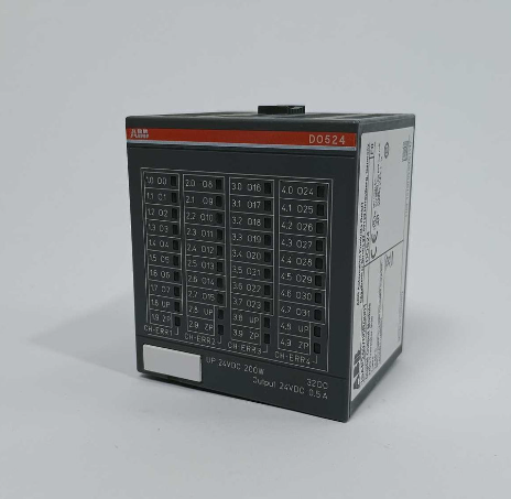
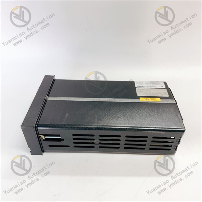
Functions and Applications: As an analog control module, IISAC01 is mainly used in industrial automation control systems to process and control analog signals. For example, in the field of process control, it can precisely control and adjust analog process parameters such as temperature, pressure, and flow rate. In the scenario of motor control, it can ensure the stable operation and protection of the motor by monitoring and controlling analog signals. In addition, it can work in coordination with other devices in the Bailey INFI 90 system, such as the BRC-100 bridge controller, to achieve more complex control functions and system integration. Appearance Dimensions: The estimated shipping dimensions are 4.0 inches x 6.0 inches x 10.0 inches (10.2 cm x 15.2 cm x 25.4 cm), and the weight is approximately 1 pound 11.1 ounces (0.8 kg).
The fault diagnosis of Bailey IISAC01 can be carried out from the following aspects: 1. Appearance Inspection: Check whether there is obvious damage to the appearance of the module, such as a cracked housing, burnt marks, etc. Check whether the connection terminals on the module are loose, oxidized, or damaged, and ensure that all cable connections are firm and intact. Check whether the status of the indicator lights on the module is normal. Different indicator light colors and flashing patterns may represent different operating statuses or fault information. Refer to the module manual to interpret the meanings of the indicator lights. 2. Power Supply Inspection: Use an appropriate measuring tool (such as a multimeter) to measure whether the power supply voltage of the module is within the specified range (24 - 240V AC/DC). If the power supply voltage is abnormal, check whether there are problems with the power supply line, fuse, etc. If the power supply voltage is normal but the module still cannot work properly, it may be that the internal power supply circuit of the module has a fault.
3. Signal Input Inspection: For analog input signals, use a signal generator or a known accurate signal source to input standard analog signals (such as 4 - 20mA current signals, 0 - 10V voltage signals, etc.), and check whether the module can correctly receive and process these signals. Through the communication interface of the module or related monitoring devices, check whether the displayed value of the input signal by the module is consistent with the actual input value. If there is a large deviation in the displayed value or no display, it may be that the signal input channel has a fault, such as a damaged input circuit or a faulty sensor. 4. Signal Output Inspection: Send a control command to the module to require it to output the corresponding analog signal, and then use a measuring tool to measure whether the output signal is normal. Check whether the range and accuracy of the output signal meet the requirements. If the output signal is abnormal, it may be that there is a problem with the output circuit of the module, or there is an error in the control logic.
5. Communication Inspection: If the module supports the communication function, check whether the communication connection is normal, including the communication cable, interface, etc. Use a communication testing tool or related software to try to communicate with the module and check whether a connection can be successfully established and the status information of the module can be read. If the communication fails, check whether the communication parameter settings (such as baud rate, address, etc.) are correct and whether there is communication interference.
6. Function Testing: According to the functional characteristics of the module, carry out relevant function tests. For example, test whether functions such as dynamic disconnection detection and sensor short-circuit monitoring are normal. By simulating actual fault situations (such as disconnecting the sensor connection, simulating a short circuit, etc.), observe whether the response of the module meets the expectations. 7. Software and Configuration Inspection: Check whether the software version of the module is the latest version. If not, consider upgrading the software to solve possible known problems. Check whether the configuration parameters of the module are correctly set, such as the measurement range, alarm threshold, etc. Incorrect configuration parameters may cause the module to work abnormally. 8. Comparison and Replacement: If there are multiple modules of the same type in the system, the suspected faulty module can be compared and tested with the normally working module. Install the faulty module in the position of the normal module and observe whether the fault shifts; install the normal module in the position of the faulty module to see if it can work normally to determine whether the fault lies in the module itself. If the cause of the fault still cannot be determined after the above inspections and tests, consider replacing the module and use a new module to verify whether the fault is caused by the damage of the original module.