Description
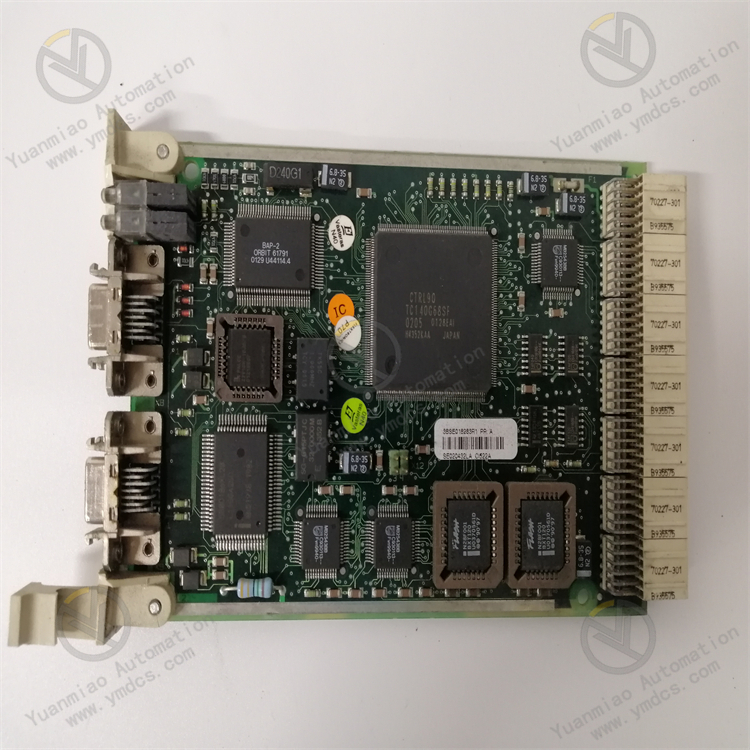
The ABB CI865K01 (3BSE040795R1) is a high-performance PROFINET communication interface module, part of the ABB AC 800M control system, primarily used to connect controllers to PROFINET networks.
1. Communication Protocols and Compatibility
PROFINET Standard Support
- Compliant with the PROFINET IO V2.3 standard, supporting Real-Time (RT) and Isochronous Real-Time (IRT) communication, suitable for industrial automation scenarios with extremely high time synchronization requirements (e.g., motion control, high-speed production lines).
- Can function as a PROFINET IO Controller or Intelligent Device (I-Device) for flexible integration into PROFINET networks.
Device Compatibility
- Supports seamless communication with PROFINET slave devices from major manufacturers (e.g., sensors, actuators, drives, third-party controllers).
- Compatible with other ABB PROFINET modules (e.g., DI/DO, AI/AO modules) and third-party PROFINET devices.
2. Performance and Functional Features
High Real-Time Performance and Reliability
- In IRT mode, the communication cycle can be as low as 1 ms, with synchronization accuracy up to 1 μs, meeting the needs of high-speed motion control and precise synchronization.
- Supports redundant network configuration (dual-port switch) to ensure seamless switching during network outages and enhance system reliability.
Data Processing Capability
- Supports a maximum of 1,440 bytes of input/1,440 bytes of output process data, enabling connection to a large number of distributed I/O devices.
- Supports asynchronous communication (S7 communication, TCP/IP, UDP) for transmitting parameters, diagnostic data, or communicating with supervisory computers (e.g., SCADA, MES).
Time Synchronization and Diagnostics
- Supports IEEE 1588 v2 precise clock synchronization to ensure time consistency across the network.
- Built-in comprehensive diagnostic functions, enabling real-time monitoring of network status and module faults (e.g., link interruptions, slave device failures) via LED indicators and ABB Control Builder software.
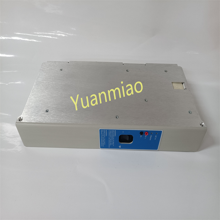
3. Hardware Design and Installation
Compact Modular Design
- Can be installed on ABB AC 800M controller racks (e.g., PM861/PM866 CPU modules) and communicates with the controller via the backplane bus.
- Physical interfaces: 2 PROFINET RJ45 ports (supporting auto-cross connection), enabling direct connection or network expansion via switches.
Environmental Adaptability
- Operating temperature: -20°C ~ +60°C, suitable for harsh industrial environments.
- Protection level: IP20 (rack-mounted), meeting installation requirements in standard control cabinets.
4. Software Configuration and Integration
Configuration Tools
- Uses ABB Control Builder M software for network configuration, parameter setting, and diagnostics, supporting import of GSDML files (PROFINET device description files) for integrating third-party slaves.
- Can be used with ABB’s Automation Builder or third-party engineering tools (e.g., TIA Portal) to achieve cross-platform system integration.
Programming and Communication Functions
- In ABB AC 800M controllers, communication function blocks (FBs) are called via IEC 61131-3 programming languages (e.g., Ladder Diagram LD, Structured Text ST) to implement data reading/writing and control logic.
- Supports PROFINET Device Replacement (DR) and Firmware Over-The-Air (FOTA) to reduce downtime.
5. Application Scenarios
- Manufacturing: Automotive production lines, electronics assembly, packaging machinery (high-speed synchronization control).
- Process Automation: Distributed control systems (DCS) in chemical, pharmaceutical, and food/beverage industries.
- Motion Control: Real-time communication with robots and servo drive systems (e.g., integration with ABB IRC5 robot controllers).
- Energy and Infrastructure: Monitoring and data acquisition (SCADA) in smart grids and wastewater treatment plants.

Technical Parameters
- Communication Function: Satt ControlNet communication interface for AC 800M systems, bridging different bus standards used on AC 800M and Satt ControlNet.
- I/O Scanning Capability: Can handle I/O scanning for up to 31 distributed I/O systems.
- Electrical Parameters: Typical 24V power consumption of 120mA.
- Mechanical Parameters:
- Dimensions: 185mm (H) × 59mm (W) × 127.5mm (D) [7.3in. × 2.3in. × 5.0in.].
- Weight: Approximately 700g (1.5lbs) including the base.
- Hot Swap Function: Supports online replacement (hot swapping) with no pre-installation configuration required.
- CEX Bus: Maximum 4 units on the CEX bus.
- Connector Type: BNC.
- Environmental Parameters:
- Operating temperature: 55°C.
- Protection level: IP20 per EN 60529 and IEC 529 standards.
How to Install and Configure the ABB CI865K01 3BSE040795R1 Module?
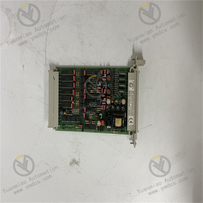
1. Module Overview
- Model: CI865K01 (3BSE040795R1)
- Type: Communication interface module (typically for PROFIBUS DP or fieldbus communication).
- Application: Connects PLCs with field devices (e.g., sensors, actuators) to enable data exchange.
2. Installation Steps
Hardware Installation
- Tools Required: Screwdriver, anti-static wristband, module mounting rail (e.g., DIN rail).
- Procedure:
- Power Interface: Connect a DC power supply matching the module’s voltage requirements (e.g., 24V DC, note positive/negative polarity).
- Communication Interface: Connect the master station (e.g., PLC) and slave devices via PROFIBUS DP cables, ensuring proper termination resistor setup (typically enabled on the first and last modules in the bus).
- Grounding: Reliably ground the module’s grounding terminal to reduce electromagnetic interference.
- Power Off: Ensure the control system is powered off to avoid electric shock or module damage.
- Install Rail: Secure the DIN rail in a suitable position inside the control cabinet.
- Fix Module: Clip the CI865K01 module onto the rail and secure it with screws (ensure the module is aligned with the slot).
- Cable Connections:
System Integration
- Installation Location: Typically inserted into the designated slot of the controller rack (e.g., PM866 controller rack for ABB AC 800M) to ensure good contact with the backplane bus.
- Notes:
- The module’s installation direction must match the rack slot markings to avoid pin damage from forced insertion.
- If the module supports hot swapping, it can be replaced while the system is running; otherwise, power off before replacement.
3. Parameter Configuration
Software Tools Preparation
- Required Software:
- ABB Control Builder M (for AC 800M system configuration).
- PROFIBUS configuration tools (e.g., Siemens SIMATIC Manager or ABB-specific tools).
- Driver Installation: Ensure the software has loaded the GSD file for the CI865K01 module (download from the ABB official website).
Configuration Steps (Taking AC 800M as an Example)
- Create Project: Open Control Builder M, create a new project, and add the controller (e.g., PM866).
- Insert Module: Drag and drop the CI865K01 module into the corresponding slot in the rack configuration interface; the software will automatically recognize the module model.
- Set Communication Parameters:
- Bus Type: Select PROFIBUS DP (based on the module’s supported protocol).
- Station Address: Set a unique address for the module on the bus (typically 0–126, consistent with the hardware DIP switch).
- Baud Rate: Match the bus speed (e.g., 9.6 kbps, 12 Mbps) with the slave devices.
- Profile: Select the module-supported profile (e.g., DP-V0, DP-V1).
- Add Slave Devices: Scan and add slave devices (e.g., inverters, I/O modules) in the PROFIBUS network, and assign input/output addresses.
- Download Configuration: Download the project configuration to the controller; the module status indicators (e.g., RUN, COM) should show normal status (green steady or blinking).
4. Status Inspection and Fault Troubleshooting
Indicator Lights
| Indicator | Status | Description |
|---|---|---|
| PWR | Green steady on | Power normal |
| RUN | Green blinking (1Hz) | Module running normally |
| COM | Green periodic blink | Communication normal |
| ERROR | Red steady on | Module fault (check wiring/config) |
| BUSFAULT | Red blinking | Bus fault (e.g., cable break, address conflict) |
Common Issues and Solutions
- Communication Failure:
- Check bus cable connections and ensure termination resistors are enabled.
- Verify that the module and slave devices have matching addresses, baud rates, and protocols.
- No Power to Module:
- Measure power voltage and check fuses or power switches.
- Configuration Download Failure:
- Ensure software version is compatible with module firmware; try updating the module firmware via Control Builder M.