Description
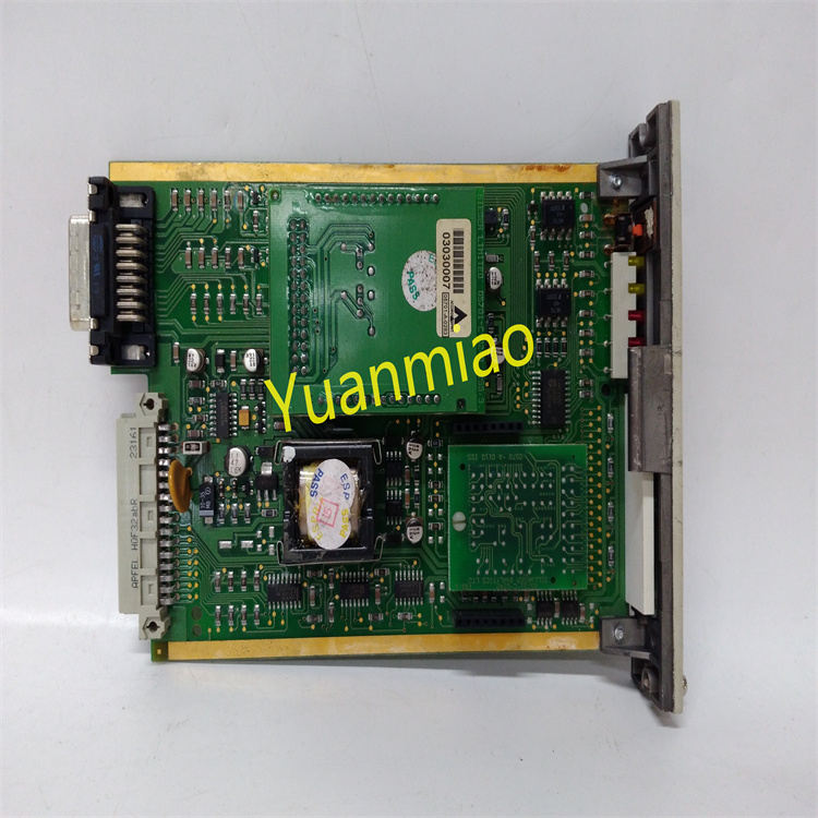
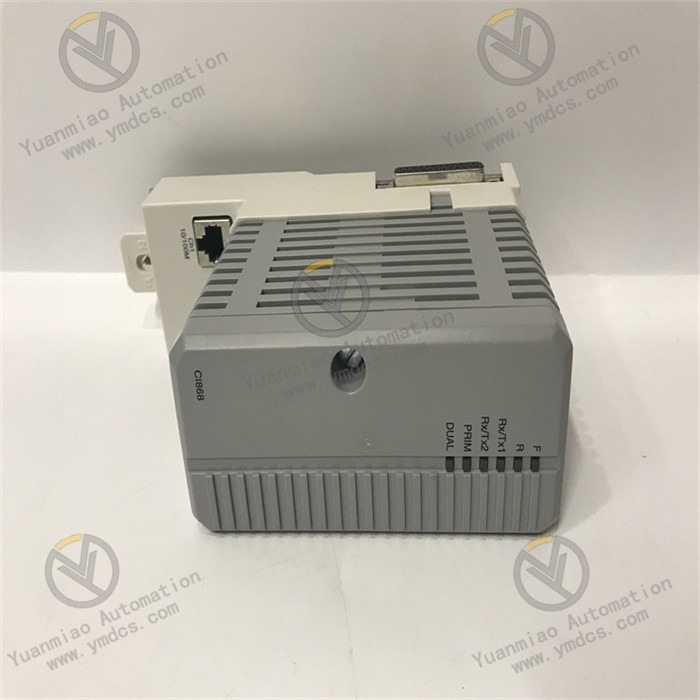
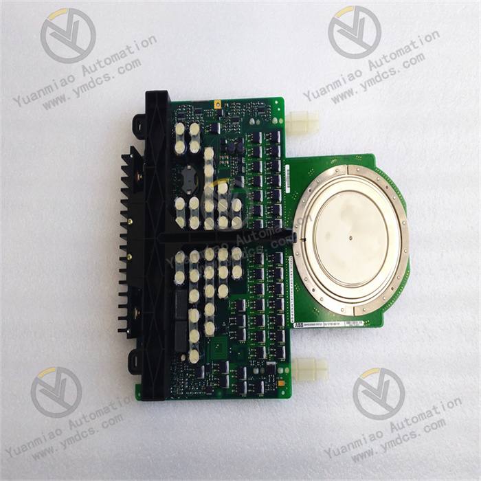
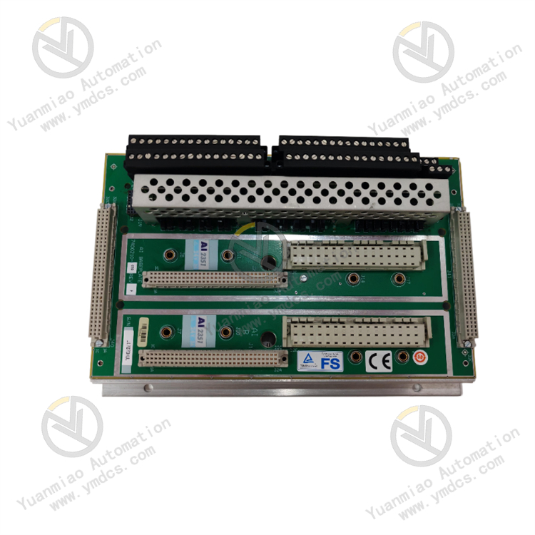
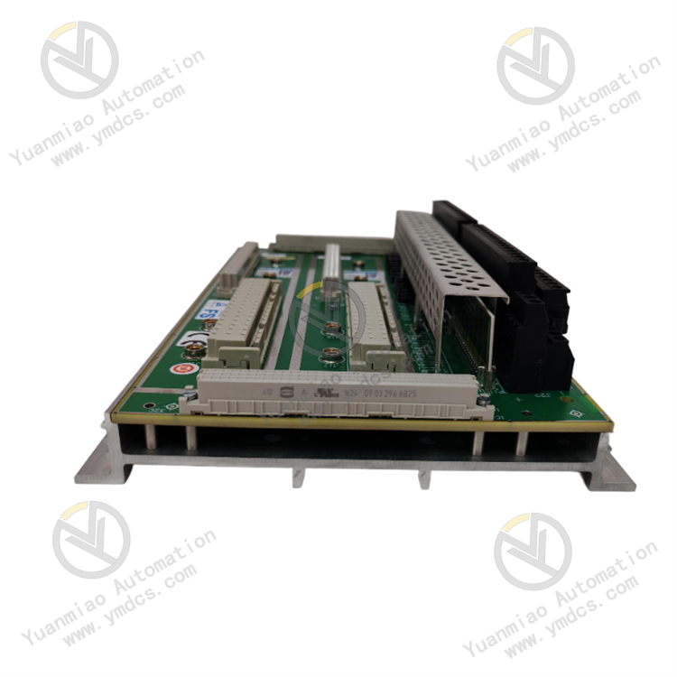
TRICONEX AI2351 is a high-performance analog input module commonly used in industrial control systems such as Safety Instrumented Systems (SIS). It supports multiple signal types including voltage, current, thermocouples, and RTDs (resistance temperature detectors), and features high reliability and anti-interference capabilities.
Features and Advantages
High-Precision Measurement: As an analog input module, it accurately measures and converts analog signals from field sensors (e.g., temperature, pressure, flow) to provide precise data for control systems.
Multiple Input Types Support: It likely supports various analog input signals (e.g., 0-10V, 4-20mA) to adapt to output signals from different sensors, facilitating connection with various field devices.
Isolation Function: Equipped with electrical isolation, it separates input signals from other parts of the control system to prevent electrical interference and fault propagation, improving system stability and anti-interference capabilities.
Technical Parameters
- Operating Voltage: 220V
- Output Frequency: 50kHz
- Input Characteristics: As an analog input module, it receives analog signals from field sensors and features advanced filtering to reliably convert sensor signals into digital data, minimizing noise interference and ensuring accurate and stable readings.
- Module Design: Designed for durability and precision, its rugged construction withstands extreme temperatures, vibrations, and other environmental stresses, ensuring stable performance in harsh industrial environments.
- Customization: Supports customizable processing options, allowing configuration of tailored solutions for specific application requirements.
Application Areas
Power Systems: Applied in power plants and substations to monitor parameters such as voltage, current, and power factor, as well as to monitor and control the status of power generation equipment and transmission lines.
Process Control: Widely used in systems requiring precise control of process parameters (e.g., temperature, pressure, flow, level). It provides feedback to control systems by real-time acquisition of analog signals, enabling stable process control.
Safety Instrumented Systems (SIS): Due to its high reliability, it can be used in SIS to monitor and protect critical parameters in hazardous environments, ensuring safe production.

Operation Guide
Installation
- Location Selection: Choose an appropriate installation location based on system requirements and space layout. Ensure the module is installed in a dry, well-ventilated environment with suitable temperature, away from strong vibrations, shocks, or electromagnetic interference.
- DIN Rail Mounting: The module typically uses DIN rail mounting. Clip the module onto the DIN rail and secure it with rail clamps or screws to ensure good contact and prevent looseness.
Wiring
- Power Connection: Connect the appropriate power supply as required by the module (usually 220V AC to the power input terminal). Ensure correct and secure wiring to avoid short circuits or poor contact.
- Input Signal Connection: Connect analog input signals from sensors or other sources to the corresponding input channels. Ensure correct wiring, matching the signal type (voltage, current, temperature, etc.) with the module's input channel configuration, and pay attention to signal polarity and range.
Configuration
- Hardware Configuration: Set basic parameters (e.g., number of channels, input signal type, range) via DIP switches or other hardware configuration interfaces on the module. Refer to the technical manual for specific setup instructions.
- Software Configuration: Use corresponding configuration software or control system software to further configure parameters (e.g., channel sampling frequency, filtering parameters, alarm thresholds) and associate the module with other devices or programs in the control system.
Commissioning and Testing
- Power-On Check: After installation and wiring, power on the module and check if the power indicator lights normally. Inspect for abnormal heating, smoke, or odors. If issues are found, power off immediately and troubleshoot.
- Signal Testing: Input known analog signals to the module's channels using a signal generator or test equipment. Verify through configuration software or the control system's monitoring interface that the module correctly receives, processes, and displays the signals. Adjust signal magnitude and type to check measurement accuracy and response characteristics.
- Function Testing: Perform corresponding function tests (e.g., check if the alarm function works by exceeding set thresholds to trigger alarms; test communication functions to ensure normal data exchange with other devices).
Operation and Maintenance
- Daily Monitoring: Regularly monitor the module's operating status during system runtime, including input signal values, indicator lights, and alarm messages. Promptly address anomalies such as signal loss or module faults.
- Periodic Maintenance: Clean the module surface, check wiring tightness, and inspect heat dissipation according to the maintenance plan. Regularly calibrate and test the module to ensure optimal performance.
- Fault Handling: If a fault occurs, initially diagnose the cause based on fault indicators, alarm messages, and system diagnostics. Refer to the technical manual or contact the supplier's technical support for further troubleshooting. Ensure safety during fault handling to avoid misoperations affecting other devices or systems.
Common Faults and Solutions
1. Module Power Failure
- Symptoms: Module indicators are off, or the power indicator (e.g., PWR) is 熄灭. The system reports "Power Loss" or "Module Power Fault."
- Causes: Loose or disconnected power supply lines, abnormal voltage, poor power interface contact, or internal power module damage.
- Solutions:
- Check power input terminals, ensure voltage meets requirements (e.g., 24VDC ±10%), and tighten terminals.
- Replace the power adapter or inspect the control cabinet's power supply circuit.
- If the power supply is normal but the module is unresponsive, it may indicate internal failure; contact the supplier for replacement.
2. Communication Failure (with Controller/Backplane)
- Symptoms: Abnormal flashing of status indicators (e.g., COM, STATUS) or fault codes. The system cannot recognize the module, or communication interrupts data reading.
- Causes: Poor backplane slot contact, communication bus failure, incorrect module address settings (e.g., DIP switch address mismatch with system configuration), or damaged/loose communication cables.
- Solutions:
- Power off and reinsert the module to ensure tight backplane slot connection.
- Check module address settings (e.g., DIP switches) and confirm consistency with the control system.
- Replace communication cables or inspect the backplane communication bus for short circuits or oxidation.
- If multiple modules have communication issues, troubleshoot the backplane or controller.
3. Abnormal Analog Input Signals (Data Jumps, Large Deviations, or No Signal)
- Symptoms: Significant fluctuations in input signal values, deviations exceeding allowable ranges (e.g., ±0.5% FS), or constant zero/fixed values.
- Causes: Faulty signal sources (e.g., sensors, transmitters), incorrect wiring (e.g., reversed polarity, mixed signal/power lines), electromagnetic interference to signal cables, damaged module channels, or configuration errors (e.g., mismatched signal type/range).
- Solutions:
- Use a multimeter to verify stable output from sensors/transmitters (e.g., 4-20mA signals).
- Check wiring compliance (e.g., compensating cables for thermocouples, three-wire connections for RTDs) and avoid ground loops.
- Shield signal cables, keep them away from interference sources, or replace with shielded cables.
- Verify module channel parameters (signal type, range, filtering time) in system configuration, recalibrate, or enable redundant channels.
- If a single channel fails, switch to a spare channel; replace the module for multi-channel issues.
4. Module Overheating or Abnormal Temperature
- Symptoms: Excessive module surface temperature (beyond 0~60°C) or system "Over Temperature" alarms.
- Causes: Poor control cabinet ventilation, high ambient temperature, insufficient installation spacing affecting heat dissipation, or internal component aging/short circuits.
- Solutions:
- Check cooling fans, improve ventilation, or install air conditioners to lower ambient temperature.
- Ensure adequate spacing (e.g., ≥25mm) from adjacent devices for heat dissipation.
- Power off and inspect for burnt components or bulging capacitors; replace the module if damaged.
5. Redundancy Function Failure (if supported)
- Symptoms: Inconsistent primary/backup module status or data loss during switching, with system "Redundancy Fault" alarms.
- Causes: Incorrect redundancy wiring, mismatched module versions, or failed primary/backup synchronization (e.g., communication link faults).
- Solutions:
- Check redundancy cable connections and ensure identical module models/firmware versions.
- Re-initialize redundancy configuration or perform a "synchronization" operation in the system.
- Contact technical support for frequent issues, possibly due to hardware compatibility.
Maintenance Recommendations
- Regular Inspections: Monthly checks of indicator lights, terminal tightness, and heat dissipation; annual functional tests (e.g., signal calibration, redundancy switch testing).
- ESD Protection: Wear anti-static wristbands during module handling to prevent electrostatic damage.
- Spare Parts Management: Store spare modules in dry, non-corrosive environments and test them periodically.
- Documentation: Record fault history, replacement times, and configuration parameters for quick troubleshooting.