Description
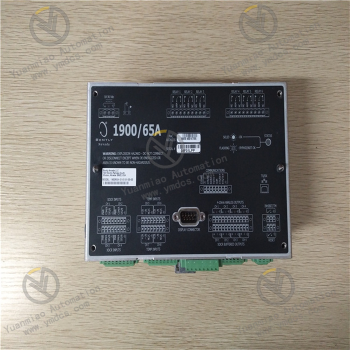
The 1900/65A series instruments are designed for the vibration monitoring of rotating machinery. They are capable of providing high-precision vibration measurement and protection functions, and are suitable for rotating equipment in various industrial fields, such as steam turbines, compressors, motors, etc. Technical Parameters Measurement range: Usually, the measurable vibration amplitude range is 0 - 50 mils (peak-to-peak) or higher, depending on the type and configuration of the sensor. Frequency range: The effective measurement range of vibration frequencies is generally 5 - 1000 Hz, which can cover the common vibration frequencies of most rotating machinery. Input characteristics: It supports the input of various types of vibration sensors, such as accelerometers, velocity sensors or displacement sensors, and can be selected according to the actual measurement requirements. Output signal: It provides standard analog output signals, such as 4 - 20 mA current signals, which can be conveniently interfaced with other control systems or data acquisition devices. At the same time, it may also have digital output interfaces, such as RS - 485 or Profibus, etc., for more complex system integration. Accuracy: The measurement accuracy is usually high, reaching ±1% or better, ensuring reliable vibration monitoring data. Operating temperature: The general operating temperature range is - 40℃ to + 85℃, which can adapt to various harsh industrial environments.
Functional Features Dual-channel measurement: This instrument has two independent measurement channels, which can simultaneously monitor the vibration signals in two different directions or positions, providing richer data for a comprehensive assessment of the vibration status of rotating equipment. Alarm and protection functions: Multiple alarm thresholds can be set. When the vibration value exceeds the preset alarm limit or danger limit, the instrument can promptly send out alarm signals to remind the operator to take corresponding measures. At the same time, protection actions such as shutdown or load reduction can be triggered through relay output and other means to protect the equipment from damage. Signal processing and analysis: It has advanced signal processing functions, which can filter, amplify, integrate and other processing of the input vibration signals to extract useful vibration characteristic information. In addition, it may also provide some basic vibration analysis functions, such as spectrum analysis, time-domain waveform display, etc., to help engineers better understand the vibration situation of the equipment. Self-diagnosis function: It has a self-diagnosis ability and can monitor the working status of the instrument itself in real time, such as whether the sensor connection is normal and whether the power supply is stable. Once a fault is detected, the instrument will send out corresponding fault alarm information, facilitating maintenance personnel to quickly locate and troubleshoot the problem.
Working Principle: Signal acquisition: Signals are collected through vibration sensors and temperature sensors installed on the equipment. The vibration sensors can convert the vibration signals of the equipment into electrical signals. For example, the accelerometer converts the vibration acceleration into an electrical signal, the velocity sensor converts the vibration velocity into an electrical signal, and the displacement sensor converts the vibration displacement into an electrical signal. The temperature sensor converts the temperature signal of the equipment into an electrical signal. For example, the thermocouple or thermal resistance generates corresponding voltage or resistance change signals according to the temperature change. Signal transmission: The sensors transmit the collected electrical signals to the monitor. These signals are transmitted to the input port of the 1900/65A monitor through cables or other transmission media. Signal processing and analysis: The monitor has signal processing and analysis functions inside. It first performs analog-to-digital conversion on the input electrical signals to convert analog signals into digital signals for digital processing. Then, various analysis algorithms are used to process the digital signals, such as calculating parameters like the amplitude, frequency, and phase of the vibration, and linearization processing and compensation of the temperature signal. Through these processing and analysis, parameters such as the vibration level and temperature status of the equipment can be determined. Comparison and judgment: The processed signal parameters are compared with the preset alarm thresholds. Users can set different alarm thresholds in the monitor according to the operating requirements and safety standards of the equipment, such as warning thresholds and danger thresholds. If the vibration parameters or temperature parameters of the equipment exceed the preset alarm thresholds, the monitor will determine that the equipment has an abnormal situation. Alarm and output: When the equipment has an abnormal situation, the monitor sends out alarm signals through relay output and other means. The relay can control external audible and visual alarms, or transmit the alarm signals to other control systems or monitoring centers to notify the operator to take corresponding measures. At the same time, the monitor can output the processed data to other devices, such as recorders, distributed control systems (DCS), supervisory control and data acquisition systems (SCADA), etc., for further data analysis and recording. Data recording and storage: The monitor can record the collected data, processed results, event information, etc., and store them in the internal memory. These data can be used for subsequent fault diagnosis, equipment operation trend analysis, and maintenance management. In addition, the monitor also supports transmitting the data to external devices or computers through the communication interface for long-term storage and in-depth data analysis.

The Bently Nevada 1900/65A is a vibration monitor for mechanical condition monitoring. The following is the general usage method of its fault diagnosis function:
Basic settings and preparations
Familiarize with equipment parameters: Understand the various setting parameters of the 1900/65A, such as the measurement range, alarm thresholds, sensor types, etc. These parameters are usually configured during the installation and commissioning of the equipment, and the current settings can be clarified by referring to the equipment manual or relevant technical documents.
Connection and inspection: Ensure that the monitor is correctly connected to the sensor, and the installation position of the sensor meets the requirements to accurately measure the vibration situation of the equipment. Check whether the power supply is normal and whether the equipment is turned on and in normal working condition.
Real-time monitoring and data viewing
Observe the displayed data: The 1900/65A usually has a display screen that can display relevant vibration data in real time, such as vibration amplitude, frequency, etc. The operator should regularly observe these data to understand the vibration status of the equipment.
Trend analysis: Utilize the trend analysis function of the monitor to view the change trend of the vibration data over time. This helps to detect the gradual changes in the vibration of the equipment and predict potential faults in advance. For example, if the vibration amplitude gradually increases, it may indicate that there are potential problems with the equipment.
Alarm and event recording
Set alarm thresholds: Set appropriate alarm thresholds according to the operating requirements and safety standards of the equipment. When the vibration data exceeds the set thresholds, the monitor will send out alarm signals to remind the operator.
View alarm information: When an alarm occurs, view the alarm information displayed on the monitor, including the type of alarm (such as high amplitude alarm, abnormal frequency alarm, etc.) and the alarm time, etc. At the same time, check the event records to understand the specific situation of the alarm and the relevant data changes before and after.
Fault diagnosis and analysis
Spectrum analysis: Some models of 1900/65A have a spectrum analysis function, which can decompose the vibration signal into different frequency components for analysis. By observing the spectrum diagram, it can be judged whether there are abnormal frequency components and whether these frequencies are related to the operating characteristic frequencies of the equipment. For example, the appearance of abnormal frequencies related to multiples of the equipment's rotation frequency may indicate problems such as unbalance, misalignment, or bearing faults.
Comparison and reference: Compare the current vibration data with the historical data when the equipment is operating normally, or compare it with the reference data of similar equipment. If obvious deviations are found, the possible causes can be further analyzed.
Comprehensive judgment: Conduct comprehensive analysis and judgment by combining the operating conditions of the equipment, maintenance records, and other relevant monitoring data (such as temperature, pressure, etc.). For example, abnormal vibration accompanied by an increase in equipment temperature may point to more specific fault causes.
Troubleshooting and maintenance suggestions
Take actions based on the diagnosis results: Formulate corresponding troubleshooting measures according to the results of the fault diagnosis. This may include further inspection, repair, or adjustment of the equipment, such as correcting the dynamic balance of the unbalanced rotor and realigning the misaligned coupling.
Record and feedback: Record the process and results of the fault diagnosis in detail, including the discovered problems, the measures taken, and the final treatment effect. These records have important reference value for subsequent equipment maintenance and fault analysis, and also help to continuously optimize the fault diagnosis method and improve the reliability of the equipment.