Description
GE DS200TCQCG1BKG
I. Overview
The GE DS200TCQCG1BKG is an outstanding industrial control module that holds a significant position in the field of industrial automation systems. It is meticulously designed to address complex and critical industrial scenarios such as gas turbine and steam turbine control systems, analog input expansion, and driver control. As a crystallization of GE's advanced technology, this module integrates cutting-edge digital signal processing technology and built-in comprehensive safety functions, enabling it to maintain stable and reliable operation in harsh and variable industrial environments.
In terms of its series affiliation, the DS200TCQCG1BKG is a vital component of GE's Mark V and Mark VI gas turbine control system series, while also playing a key role in the RST overflow board series. This allows it to exert unique value in different types of industrial control system architectures and adapt to various system configuration requirements. Its application fields are extremely wide-ranging:
- In the power industry's power plants and substation control systems, it precisely processes various analog signals to assist in monitoring the operating status of power generation equipment and ensure stable power supply.
- In the petrochemical industry, facing complex chemical installations, it accurately controls analog signals related to numerous process parameters, laying a solid foundation for safe and efficient production.
- On manufacturing production lines, equipment control relies on its reliable performance to ensure smooth production processes and stable product quality.
- In energy management, whether for turbine control or the implementation of energy optimization strategies, it provides indispensable signal processing support.
- In building automation scenarios such as air conditioning, lighting, and elevator control, it achieves precise control by virtue of its own characteristics, enhancing the intelligent management level of buildings.
II. Technical Parameters
1. Power Parameters
- Input Voltage: 24VDC. This voltage is compatible with most industrial power supply systems, providing basic power support for the stable operation of the module. It also has a certain adaptability to voltage fluctuations, ensuring the module can still work normally when there are certain changes in power output.
- Output Voltage: Can output voltage signals of 0~10V DC. This output range can meet the working requirements of many devices such as actuators and sensors, providing suitable voltage drive for signal transmission and control command issuance.
- Rated Current: 5A, meeting the current requirements of the module itself and some connected devices, ensuring the stability and continuity of power supply and the stable operation of each link in the system.
2. Electrical Parameters
- Analog Input:
- Number of Channels: Equipped with 16 analog input channels. The powerful multi-channel design allows the module to connect multiple different types of analog sensors simultaneously, widely collecting various analog signals, fully meeting the needs of large-scale and diversified data acquisition, and greatly enhancing the comprehensiveness and efficiency of system data acquisition.
- Input Voltage Range: The input signal range is 0 to 5V. This range covers the output signal intervals of common analog sensors, and can be adapted to the output signals of various devices such as thermocouples, thermal resistors, and various pressure, flow, and liquid level sensors, greatly enhancing the compatibility of the module with different sensors and improving the versatility of the device.
- Analog Output:
- Number of DAC Channels: Equipped with 2 DAC channels, which can output precise analog control signals, providing accurate analog drive that meets the working requirements for devices such as actuators, and is used for precise control of executive actions such as the opening of control valves and the speed of motors, realizing fine-grained regulation of industrial production processes.
- Isolation & Accuracy: The module has high signal processing accuracy, which can effectively resist interference in complex industrial electromagnetic environments and ensure the accuracy and stability of signals. Although the specific accuracy value is not explicitly mentioned, it can be inferred from its application scenarios and performance that high-precision conversion between analog and digital signals and subsequent processing and output can be achieved within the entire working range, providing a reliable data foundation for industrial applications with strict measurement accuracy requirements. At the same time, effective electrical isolation measures are taken between input and output, as well as between the device and external circuits. Although the specific value of the isolation voltage is not given, it can greatly prevent external interference signals from affecting the internal circuits of the device, while avoiding the interference generated by the device itself from affecting other equipment, ensuring stable operation in complex electromagnetic environments.
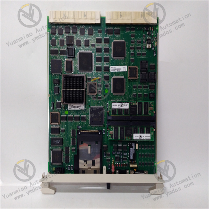
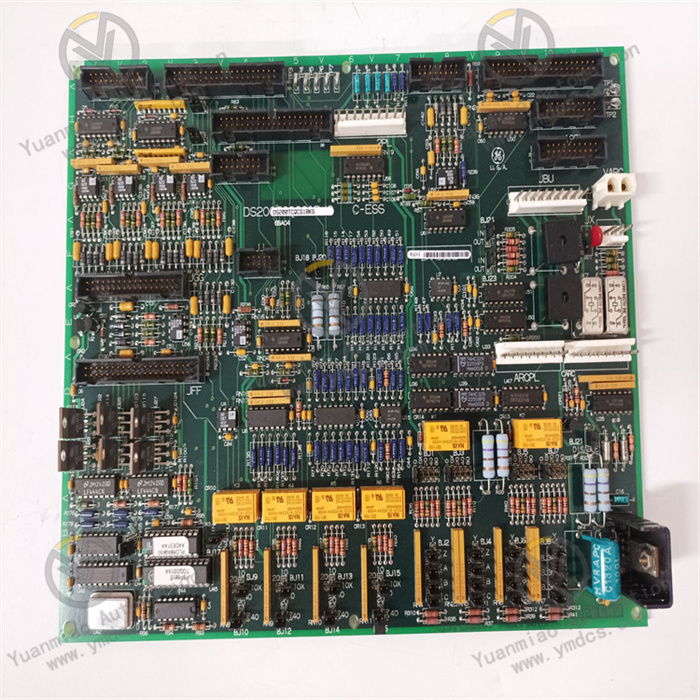
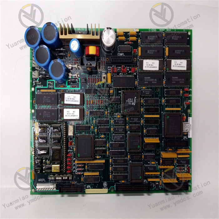
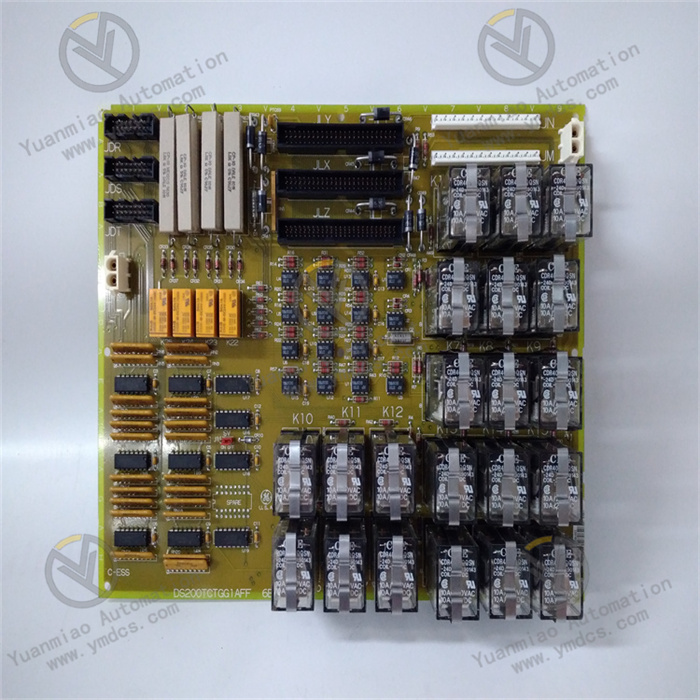
- Hardware Configuration: The board is equipped with a variety of hardware components to achieve functions. For example:
- The first 16 hardware jumpers are used to configure the output current range of the servo output, where even-numbered jumpers are responsible for selecting feedback scaling, and odd-numbered jumpers are used to select the source output resistance.
- Hardware jumpers 25 to 36 provide additional feedback scaling options for servos 1 to 4, enabling them to reach a maximum current range of ±240mA.
- BJ 17 is used to set the RS232 port for board testing; BJ 21 is the stall timer enable; BJ22 is the oscillator enable for factory testing; BJ 23 and BJ 24 are unused; BJ 18 and BJ20 limit the power supply of P15 and N15 to proximity sensors.
- In some applications, hardware jumpers JP 38 and JP 39 are used to set the magnetic sensor gain for liquid fuel flow signals.
- Additionally, it includes multiple resistor network arrays, jumper switches, DIP switches, reset buttons, as well as various capacitors, resistors, and diodes. These rich hardware configurations provide a solid support for the functional realization and flexible application of the module.
3. Communication Parameters
- Communication Interfaces & Protocols: Supports multiple communication interfaces and protocols, explicitly including Ethernet, serial communication, etc., and also supports the Modbus RTU communication protocol.
- The Ethernet interface enables the module to quickly and efficiently interact data with other network-capable devices, suitable for building large-scale industrial automation networks to achieve remote monitoring and control.
- The serial communication interface, with its characteristics of simplicity and reliability, plays a role in scenarios where the requirement for data transmission rate is relatively low, but the requirement for stability and anti-interference is high.
- The support for the Modbus RTU protocol further enhances its compatibility and interoperability with different devices, facilitating seamless docking with various PLCs, intelligent instruments, and other devices that follow this protocol to achieve accurate data transmission and effective issuance of instructions.
4. Mechanical & Environmental Parameters
- Operating Temperature Range: Can stably operate in the extreme temperature range of -40°C to 85°C. This broad temperature adaptation range allows it to work normally in various complex climatic conditions and different industrial environment temperatures worldwide. Whether in industrial facilities in cold polar regions or factories in hot desert areas, it can ensure the continuous and stable operation of the system, greatly expanding its application scenarios.
- Humidity Range: Can work reliably in an environment with a relative humidity of 5% to 95% (non-condensing), demonstrating good adaptability to humidity environments. It can effectively reduce the risk of device failure caused by humidity changes, ensuring stable operation in humid coastal area factories or industrial production workshops with large humidity changes.
- Protection Level: Reaches the IP65 protection level, with good dust-proof capability, which can effectively block dust particles from entering the interior of the module and protect the internal circuits; it also has a certain waterproof capability, able to protect against low-pressure water column spraying from all directions. Even in relatively harsh outdoor industrial environments or industrial sites with certain water vapor and mist, it can ensure the normal operation of the module and extend the service life of the device.
- Dimensions & Weight: The size is 6.5″x 4.5″x 1.5″ (approximately 16.5 cm x 11.4 cm x 3.8 cm). The compact shape design gives it significant advantages when installing in industrial control cabinets and equipment interiors with limited space, facilitating flexible layout and installation and saving valuable installation space. The weight is approximately 0.68 kilograms. The moderate weight is convenient for handling and installation operations, and it will not cause a large burden on the installation structure during equipment operation.
- Installation Method: Adopts the DIN bracket installation method, which is characterized by convenient installation and stable reliability. Through the DIN rail, the module can be quickly fixed in equipment such as control cabinets, facilitating subsequent maintenance and replacement and improving the efficiency of equipment installation and maintenance.
III. Working Principle
1. Analog Signal Input Processing Flow
When various analog signals, such as those from temperature, pressure, flow, etc., sensors are connected to the 16 analog input channels of the DS200TCQCG1BKG, the signals first enter the input buffer circuit. This circuit plays a role in preliminary isolation and buffering: on the one hand, it prevents the fluctuations, noise, etc., of the input signals from damaging the subsequent precise processing circuits; on the other hand, it enhances the driving capability of the signals, enabling them to be stably transmitted to the subsequent circuits. The signals then enter the signal conditioning circuit, where they are subject to targeted processing according to the characteristics of the input signals and subsequent processing requirements. If the input signal amplitude is low and cannot reach the effective processing range of the A/D converter, the operational amplifier will amplify it; if the signal is mixed with high-frequency noise, the low-pass filter will function to filter out the noise and improve the purity and quality of the signal. The conditioned analog signals are then sent to the A/D converter, which precisely converts the analog signals into digital signals for subsequent digital signal processing by the digital signal processor (DSP). The DSP performs a series of operations such as calibration and linearization on the converted digital signals to eliminate the possible nonlinear errors of the sensor and other errors introduced in the measurement process, and finally obtains digital signal data that can accurately reflect the measured physical quantity, providing a reliable basis for subsequent control decisions.
2. Signal Processing & Communication Collaboration Mechanism
The digital signal processor conducts in-depth analysis and complex calculations on the processed digital signal data according to the system's pre-set control strategies and algorithms, generating corresponding control instruction data. These control instruction data are packaged and encoded through the communication interface circuit in strict accordance with the supported communication protocols (such as Modbus RTU), and then sent to the host computer control system or other connected devices that need to receive data through the Ethernet or serial communication interface, realizing remote data transmission and sharing. At the same time, the module is always ready to receive instructions and parameter setting information from the host computer control system. Once these information are received, the digital signal processor will quickly dynamically adjust the signal processing flow and control strategy according to the new information, ensuring that the entire control system can adapt to different working states and changing needs in real time and maintain the efficient and stable operation of the industrial production process.
3. Analog Signal Output Control Process
When the digital signal processor receives an instruction to output an analog control signal, it transmits the corresponding digital control signal data to the D/A converter in the 2 DAC channels. The D/A converter converts the digital signal into an analog signal, which then enters the output buffer circuit. The output buffer circuit here plays a role in isolating the D/A converter from external loads, avoiding the impact of external load changes on the D/A converter and protecting its normal operation. The analog signal then enters the signal conditioning circuit, where it is amplified, filtered, etc., to adjust the signal amplitude to the range where the actuator can work normally and filter out possible high-frequency interference signals, making the analog output signal meet the strict input requirements of the actuator. Finally, the analog control signal processed through a series of steps is transmitted to actuators such as control valves and motor drivers through the analog output channel, thereby achieving precise control of various devices in the industrial production process and ensuring that the production process operates stably according to the 预定 (predetermined) process parameters and control strategies.
4. Operation of the Fault Detection & Diagnosis System
The DS200TCQCG1BKG has a built-in complete and intelligent fault detection and diagnosis mechanism. Throughout the entire process of signal acquisition and processing, it continuously and real-timely monitors key parameters such as the amplitude and frequency of input signals. Once abnormal signal conditions are found, such as the signal amplitude exceeding the normal working range, abnormal signal frequency fluctuations, or signal loss, it will immediately trigger the fault alarm mechanism to remind operators as quickly as possible. At the same time, the module will carry out a comprehensive self-inspection of its hardware circuits, including periodic and strict functional detection of key components and elements such as A/D converters, D/A converters, digital signal processors, communication interface circuits, as well as numerous hardware jumpers, resistors, and capacitors. If a hardware component failure is detected, on the one hand, it will be intuitively indicated by the relevant indicators on the board to facilitate operators in quickly locating the fault position; on the other hand, detailed fault information will be promptly sent to the host computer control system through the communication interface, so that operators can quickly carry out fault troubleshooting and repair work, minimizing equipment downtime and ensuring that the entire control system always maintains high reliability and stability, providing a strong guarantee for the continuity of industrial production.