Description
Functional Characteristics
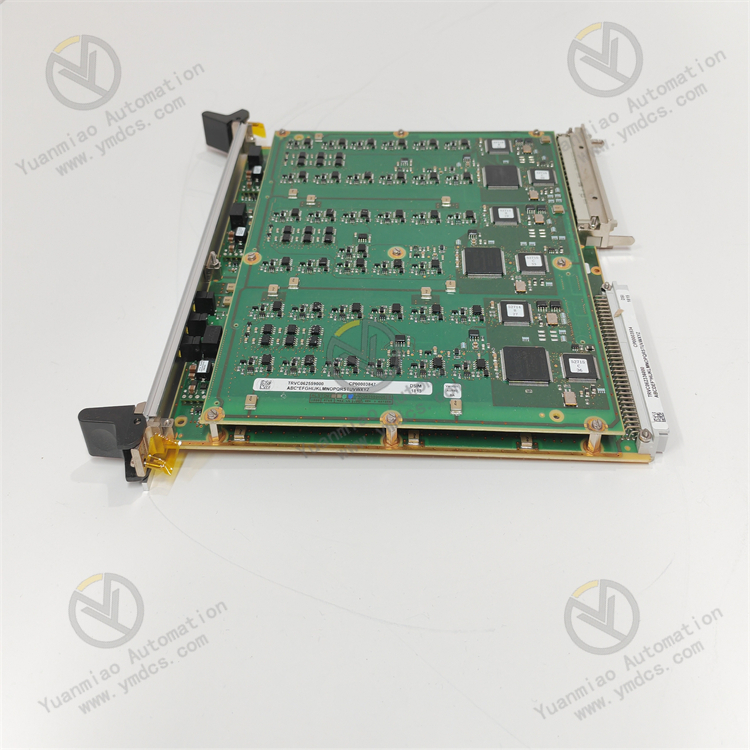
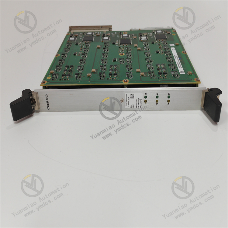
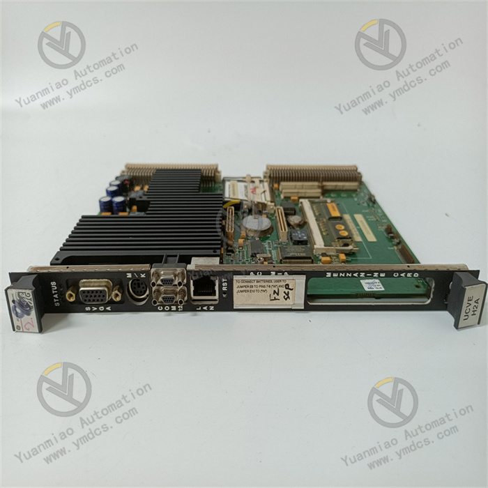
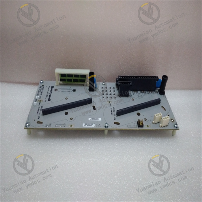
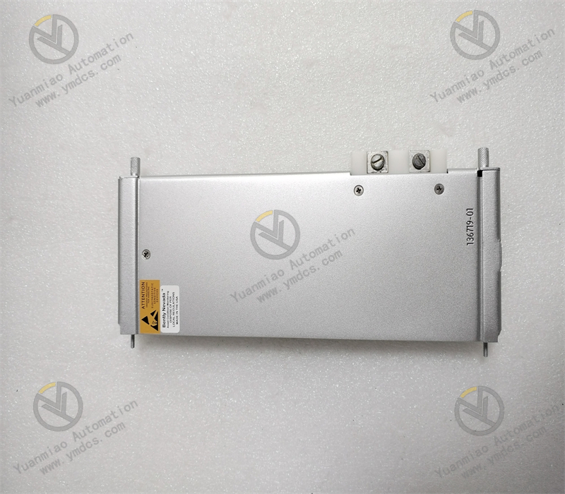
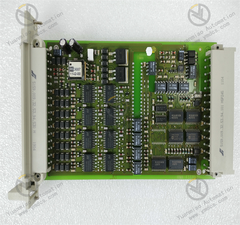
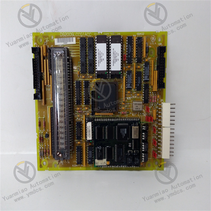
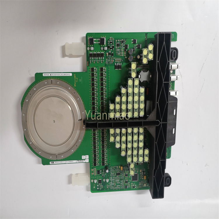
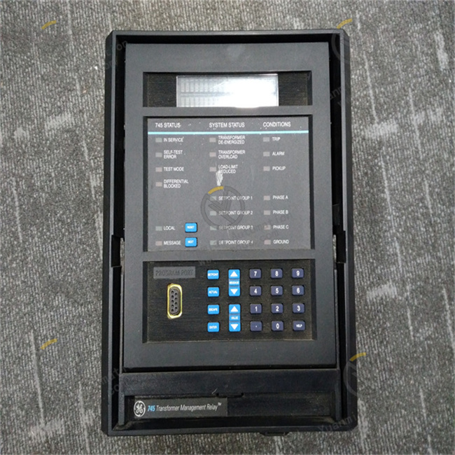
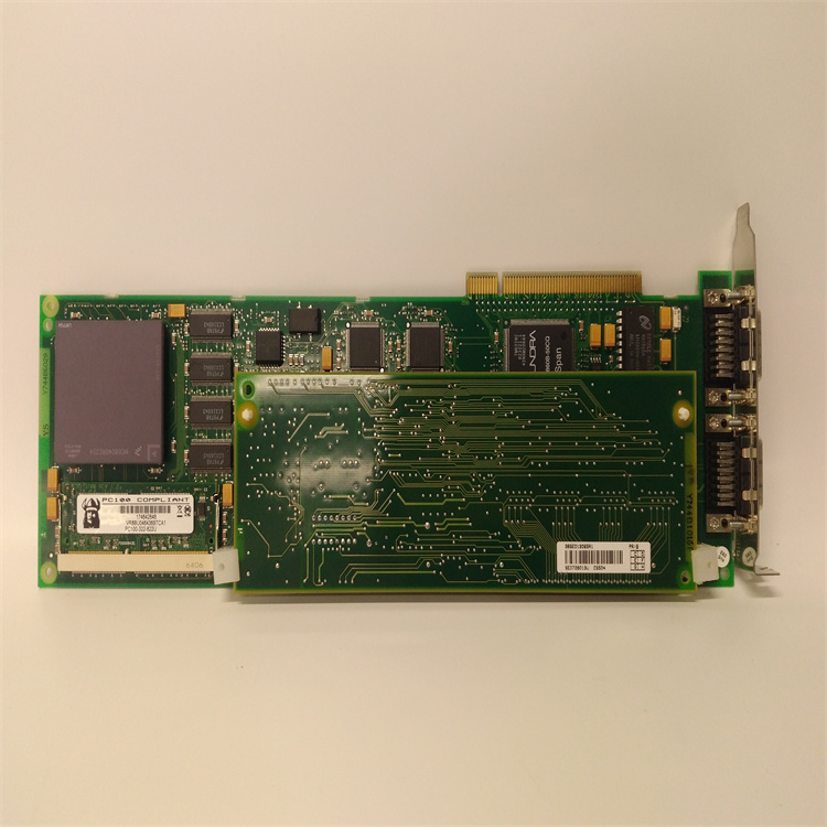
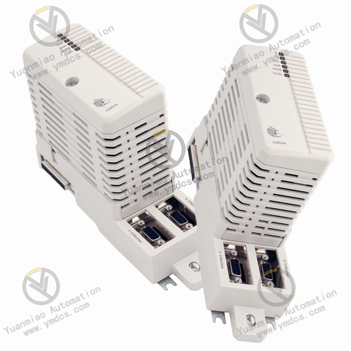
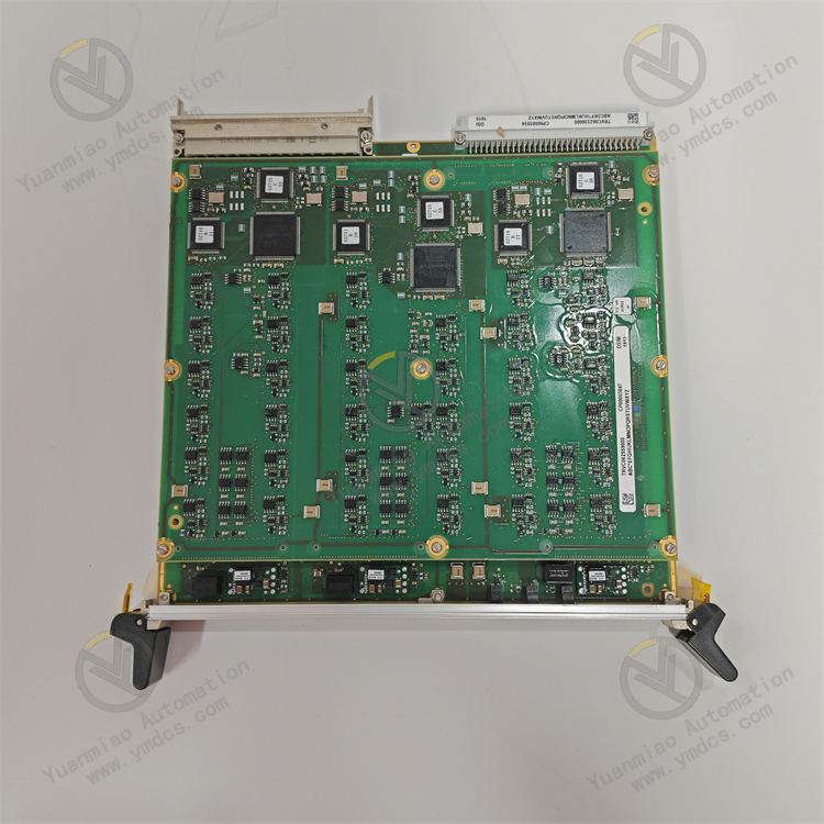
Modularity and Flexibility: Alstom's field control products are typically highly modular distributed I/O and control products suitable for various host architectures. This product may also adopt a modular design, facilitating flexible configuration and expansion according to different application scenarios and requirements. It can be easily integrated with other devices or systems to meet diverse industrial control needs.
Reliable Performance: As a global leader in power generation and transportation infrastructure, Alstom emphasizes product reliability. This product may use high-quality materials and advanced manufacturing processes, featuring sturdiness and durability. It can operate stably in harsh industrial environments, such as having strong anti-interference capabilities and adapting to a wide temperature range, ensuring long-term fault-free operation and reducing maintenance costs and downtime.
Intelligent Processing Capability: It may have a built-in intelligent processor capable of rapidly and accurately processing and analyzing input signals, and outputting corresponding control signals based on preset rules or algorithms to achieve precise control of industrial processes. For example, it may have functions such as data acquisition, processing, logical operations, and communication, enabling data interaction with upper computers or other control systems for remote monitoring and management.
Efficient I/O Functions: If involving I/O modules, it generally has efficient I/O processing capabilities, supporting multiple types of input/output signals, such as digital input/output and analog input/output. It can quickly and accurately collect status information from field devices and transmit control signals to actuators for real-time device control. Additionally, I/O terminal blocks are typically universal, allowing different types of I/O modules to be installed on the same base for easy system expansion and maintenance.
Technical Parameters
| Parameter Category | Content |
|---|---|
| Rated Voltage | Such as DC 1500V / AC 25kV (depending on the application scenario) |
| Rated Power | Such as 3000kW (traction system) |
| Operating Temperature Range | -25°C ~ +70°C |
| Protection Level | IP54 / IP65 (dust and water protection grade) |
| Communication Interfaces | MVB, CAN, Ethernet, etc. |
| Dimensions and Weight | Such as 1200mm×800mm×500mm, weight 300kg |
| Compliance Standards | EN 50155 (Railway Electronic Equipment Standard), EN 61373 (Vibration and Shock Standard), etc. |
Working Principles
- Traction Converter
- Working Principle: Converts electrical energy input from the power grid into a frequency and voltage suitable for motor operation to drive train traction motors.
- Technical Parameters: Input voltage (e.g., AC 25kV), output power (e.g., 3MW), efficiency (≥95%), protection level (IP54, etc.).
- Functional Characteristics: Energy feedback technology, high-reliability design, support for train regenerative braking.
- High-Voltage Contactor
- Working Principle: Controls the opening and closing of contacts through an electromagnetic mechanism to connect or disconnect high-voltage circuits.
- Technical Parameters: Rated voltage (e.g., 3000V DC), rated current (e.g., 1500A), breaking capacity, mechanical life (≥1 million times).
- Functional Characteristics: Strong arc extinguishing capability, vibration resistance, suitable for frequent operation scenarios.
- Signal System Components
- Working Principle: Transmits train position, speed, and other information through wireless communication (e.g., GSM-R) or track circuits to achieve train operation control.
- Technical Parameters: Communication frequency (e.g., 876-880MHz), data transmission rate, safety integrity level (SIL4).
- Functional Characteristics: Compliance with ETCS (European Train Control System) standards, fault-safe design.
Common Fault Scenarios and Solutions (for reference)
I. Electrical Faults (common in converters, contactors, etc.)
- No Power Supply or Failure to Start
- Check if the input power voltage meets the rated parameters (refer to the device nameplate).
- Replace the fuse or reset the circuit breaker, and investigate whether tripping was caused by overload.
- Tighten control circuit connections and use a multimeter to test for continuity.
- Input power failure (e.g., unstable voltage, open circuit).
- Blown fuse or tripped circuit breaker.
- Loose or poor contact in the control circuit wiring.
- Possible Causes:
- Solutions:
- Abnormal Heating or Odor
- Inspect component appearance after shutdown and replace damaged parts (professional operation required).
- Clean dust from cooling vents, test fan operation, and replace the fan if necessary.
- Disconnect power, sandblast contact points, or replace connectors.
- Aging of internal components (e.g., swollen capacitors, burnt resistors).
- Faulty cooling fan or blocked cooling vents, leading to poor heat dissipation.
- Oxidized or loose contact points, causing excessive contact resistance.
- Possible Causes:
- Solutions:
- Frequent Tripping or Protection Activation
- Check if the load is within the rated range and reduce non-essential loads.
- Use an insulation tester to detect wiring insulation resistance and repair or replace damaged wiring.
- Reset protection parameters with reference to the operation manual, and contact the manufacturer for calibration if necessary.
- Overload operation (e.g., load exceeding rated power).
- Short circuit (damaged internal wiring insulation or external load short circuit).
- Improper protection parameter settings (e.g., too low overcurrent/overvoltage thresholds).
- Possible Causes:
- Solutions:
II. Mechanical Faults (common in transmission components, connectors, etc.)
- Abnormal Vibration or Noise
- Tighten all mounting bolts after shutdown and check bracket structural stability.
- Add lubricating oil or replace worn bearings and gears, and perform regular lubrication maintenance.
- Check for fan blade deformation, adjust the mounting position, or replace the fan.
- Loose mounting bolts or unstable brackets.
- Wear of transmission components (e.g., oil shortage in gearboxes, damaged bearings).
- Deformed fan blades or interference with the housing.
- Possible Causes:
- Solutions:
- Failure to Actuate or Sticking (e.g., contactor contacts not engaging)
- Disassemble components to clean foreign matter and use rust remover on rusted areas.
- Replace springs or entire components to ensure smooth mechanical movement.
- Use a multimeter to test coil resistance; replace the coil or contactor assembly if burnt.
- Rust or foreign matter jamming in mechanical parts (e.g., dust, metal debris).
- Aging springs losing elasticity, causing incomplete contact action.
- Burnt electromagnetic coil or abnormal control signal.
- Possible Causes:
- Solutions:
III. Communication Faults (common in signal modules, sensors, etc.)
- Data Transmission Interruption or Errors
- Check cable connections for tightness, replace damaged cables, and clean interface contacts.
- Reconfigure communication parameters according to the manual to ensure consistency with the master device's protocol.
- Reset the module or update the firmware; replace the module if ineffective.
- Damaged communication cables, loose interfaces (e.g., MVB, Ethernet interfaces).
- Protocol mismatch or parameter setting errors (e.g., baud rate, address conflicts).
- Faulty internal communication chip in the module.
- Possible Causes:
- Solutions:
- Abnormal Sensor Signals (e.g., distorted position or temperature data)
- Clean the probe with anhydrous alcohol to ensure the detection area is unobstructed.
- Re-calibrate the mounting position and use special tools to adjust to the specified distance.
- Detect sensor output signals with an oscilloscope and replace the sensor if abnormal.
- Contaminated sensor probes (e.g., dust or oil blocking the detection window).
- Offset sensor mounting position, leading to detection errors.
- Faulty sensor itself (e.g., component aging, circuit damage).
- Possible Causes:
- Solutions:
IV. Safety Precautions
- High-Voltage Operation Risks: When dealing with high-voltage components (e.g., converters, contactors), always disconnect the power supply first, hang a "Do Not Close" sign, and wait for capacitor discharge (usually at least 5 minutes) before maintenance.
- Professional Qualification Requirements: Most Alstom products are critical rail transit equipment; unauthorized personnel must not disassemble or repair them to avoid safety accidents or equipment damage.
- Recording and Feedback: After each fault handling, detailed records of fault symptoms, processing steps, and replaced component information must be kept for follow-up maintenance reference. If similar faults occur frequently, contact Alstom technical support immediately to investigate design or installation hidden issues.


