Description
1. Product Overview
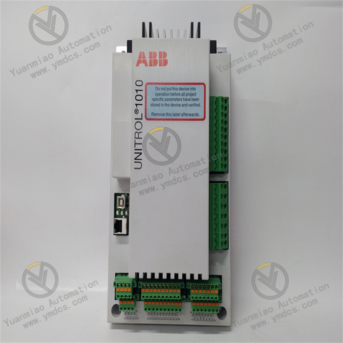
ABB UNITROL 1010 (Part No. 3BHE035301R0001) is a new‑generation digital excitation control system (Digital Excitation System / Automatic Voltage Regulator, AVR) developed by Swiss‑based ABB. Belonging to ABB UNITROL series compact digital excitation products, it is designed for excitation regulation and generator voltage control of medium‑and‑small‑sized synchronous generators, steam‑turbine generator sets, hydro‑turbine generator sets, diesel‑generator sets, synchronous condensers, synchronous motors and industrial captive power plants. This device delivers full‑range excitation and protection functions including automatic generator terminal‑voltage regulation, reactive‑power distribution, power‑factor adjustment, constant‑excitation‑current control, field‑forcing limit, under‑excitation limit, over‑excitation limit, V/F limit, Power System Stabilizer (PSS), rotor over‑temperature protection, loss‑of‑excitation protection, de‑excitation control and generator start‑stop sequence control. It serves as the core control hardware for synchronous‑generator excitation systems.
It has passed comprehensive industrial‑grade and power‑system‑grade tests: full‑load burn‑in, temperature cycling, vibration‑shock test, dielectric withstand, electromagnetic‑interference test, thyristor‑firing and rectifier‑bridge full‑load test. Supporting 7×24‑hour year‑round full‑load continuous operation, it withstands harsh cabinet‑site conditions in power plants and industrial facilities such as high enclosed temperature, dust‑humidity environment, alternating temperature cycles, strong electromagnetic interference and grid‑voltage fluctuation. Given the massive global installed base of UNITROL 1010 for medium‑and‑small‑sized synchronous‑generator units, spare‑part supply, fault replacement and system maintenance are critical for safe and stable operation of in‑service units, and constitute one of the key hardware assets for power‑plant excitation‑system retrofitting and spare‑part stocking.
2. Functional Features
2.1 Full‑digital multi‑loop excitation regulation with high voltage‑control accuracy
Equipped with high‑performance industrial‑grade CPUs and large‑capacity memory, UNITROL 1010 runs ABB’s mature digital‑excitation‑regulation algorithms and supports bumpless automatic mode switching among automatic‑voltage regulation (AVR), reactive‑power regulation (Q‑control), power‑factor regulation (cosφ‑control) and constant‑field‑current control (FCR). The regulation loop integrates a main PID regulator, lead‑lag compensation, auxiliary PSS channel, V/Hz limiter, over‑excitation limiter (OEL), under‑excitation limiter (UEL), stator‑current limiter and rotor‑overcurrent limiter. Steady‑state voltage‑regulation accuracy reaches within ±0.5 %. Dynamic‑response performance complies with IEEE 421.2 and power‑industry standards, effectively improving unit‑voltage stability and grid‑parallel‑operation performance.
2.2 Redundant fault‑tolerant architecture with bumpless fault‑time switching
The device supports dual‑redundant AVR‑channel configuration. Primary and standby regulation channels synchronize operating data, measured values, regulation outputs and status signals in real‑time via high‑speed redundant links. Upon primary‑channel failure, the standby channel takes over excitation control within milliseconds in a bumpless manner. Thyristor‑firing‑pulse outputs remain glitch‑free, with no disturbance to generator‑field‑current and terminal voltage. Maintenance personnel may replace the faulty channel online without tripping the unit. CRC check and data‑consistency monitoring are implemented on redundant links to prevent excitation anomalies caused by data desynchronization, providing core guarantee for continuous operation of large synchronous‑generator units.
2.3 Integrated thyristor‑rectifier‑bridge firing and de‑excitation control
Built‑in digital firing‑control unit for thyristor rectifier bridges directly adjusts firing angles for three‑phase fully‑controlled / half‑controlled rectifier bridges to achieve continuously‑adjustable field current. Firing circuits are isolated from rectifier bridges via optical‑fiber / shielded‑cable links for strong anti‑interference capability. The device also integrates de‑excitation‑switch control, rotor over‑voltage protection and rectifier‑cabinet monitoring (bridge‑arm fuse status, thyristor temperature, fast‑fuse condition). Regulation control and power‑loop monitoring are integrated into one unit, reducing external wiring and independent monitoring equipment.
2.4 Comprehensive online self‑diagnosis, event‑sequence and trend recording
Multi‑level self‑diagnosis covers CPU, memory, measurement loops, regulation loops, firing circuits, I/O channels, communication links and power supplies. The front‑panel LCD touch‑screen displays real‑time terminal voltage, field current, firing angle, reactive power, power factor, device temperature, channel status and fault alarms. Built‑in Sequence‑of‑Events (SOE), fault‑oscillography and trend‑recording functions allow maintenance staff to export fault waveforms and historical data via USB / Ethernet / serial port for precise fault‑location without cabinet disassembly, greatly shortening troubleshooting and repair time.
2.5 Standardized communication interfaces for seamless integration with plant‑monitoring systems
Multiple standard communication interfaces support mainstream power‑industry and industrial protocols including Modbus RTU/TCP, Profibus‑DP and IEC 61850 MMS. The regulator can directly connect to power‑plant DCS/SCADA, hydropower‑station computer‑monitoring systems and substation integrated‑automation systems to realize real‑time uploading and remote‑control of generator voltage, reactive power, field current, device status and alarm signals. Supported by dedicated ABB commissioning software (PCM600 / Composer), engineers may modify regulation parameters, view oscillography, download configurations and back‑up programs via laptop without dedicated hand‑held operators.
2.6 Industrial‑grade strong anti‑interference and wide‑range stable operation
Industrial‑reinforced electrical architecture and multi‑layer electromagnetic‑shielding deliver excellent EMC performance against rectifier‑bridge harmonics, variable‑frequency‑drive interference, power‑cable coupling interference, unit electromagnetic radiation and grid‑voltage fluctuations. The operating‑temperature range fits typical control‑cabinet environments. It withstands high‑temperature, low‑temperature, high‑humidity and aging conditions. Long‑term operation under harsh cabinet conditions including high enclosed temperature, dust‑humidity environment and continuous vibration brings no parameter degradation or loop faults, ensuring year‑round reliable excitation‑system operation.
2.7 Modular design for efficient maintenance and replacement
ABB‑standard modular plug‑in structure applies to CPU boards, I/O boards, power‑supply boards, communication boards and firing boards, featuring precise rack alignment, easy assembly and secure latching. Board dimensions, connector definitions and front‑panel layout are compatible with other UNITROL‑series models for good spare‑part commonality. ABB commissioning software enables program upload/download, parameter configuration and fault‑oscillography analysis via Ethernet / serial port without specialized tools or complex wiring, improving on‑site commissioning, retrofitting and repair efficiency.
3. Technical Specifications
3.1 Core Compatibility Parameters
| Item | Specification |
|---|---|
| Complete Part Number | 3BHE035301R0001 |
| Brand | ABB (ASEA Brown Boveri, Switzerland) |
| Product Series | ABB UNITROL‑series digital excitation‑control system |
| Product Type | Digital synchronous‑generator excitation regulator (AVR / Excitation Controller) |
| Applicable Units | Steam‑turbine generators, hydro‑turbine generators, diesel generators, synchronous condensers, synchronous motors |
| Excitation Topologies | Static‑shunt excitation, three‑machine excitation (AC exciter + static rectifier), brushless excitation, separate‑source excitation |
| Matching Hardware | Thyristor rectifier cabinet, de‑excitation switch, PT/CT, excitation transformer, generator rotor loop |
| Core Functions | AVR voltage regulation, Q/cosφ/FCR control, PSS, OEL/UEL/VHz limiting, de‑excitation control, rectifier‑bridge firing, protection interlock, self‑diagnosis |
| Typical Applications | Medium‑and‑small‑sized power stations, captive power plants, hydropower plants, captive units for metallurgical / petrochemical / coal‑mining industries, synchronous‑motor excitation |
3.2 Electrical Performance Parameters
| Item | Specification |
|---|---|
| Regulation Modes | AVR automatic‑voltage regulation, FCR constant‑field‑current control, Q reactive‑power control, cosφ power‑factor control; bumpless mode transition |
| Steady‑State Accuracy | Generator terminal‑voltage steady‑state regulation accuracy ≤ ±0.5 % |
| Measurement Inputs | Generator‑terminal‑voltage PT, stator‑current CT, field current / voltage, rotor current, unit frequency |
| Firing Output | Digital firing pulses for three‑phase fully‑controlled / half‑controlled rectifier bridges; optical‑fiber / cable‑isolated output |
| Limits & Protections | Over‑excitation limit (OEL), under‑excitation limit (UEL), V/Hz limit, stator‑current limit, rotor overcurrent, loss‑of‑excitation protection, over‑excitation protection |
| PSS Power‑System Stabilizer | Standard PSS2A / PSS2B; optional IEEE‑standard PSS models |
| Communication Interfaces | Modbus RTU/TCP, Profibus‑DP, IEC 61850 MMS, Ethernet, USB, RS‑232/RS‑485 |
| Redundancy Configuration | Dual‑AVR‑channel redundancy; automatic bumpless primary‑standby switching |
| Human‑Machine Interface | LCD touch‑screen for real‑time display of operating parameters, status, alarms and fault oscillography |
| Power Supply | Dual‑channel 220 V DC / 110 V DC or 220 V AC power supply; wide‑input‑voltage range |
3.3 Environmental & Physical Parameters
| Item | Specification |
|---|---|
| Operating Temperature | Industrial wide‑range design for enclosed power‑plant / industrial‑cabinet conditions |
| Storage Temperature | Suitable for extreme temperature during storage and transportation |
| Operating Humidity | 5 %‑95 %RH (non‑condensing); tolerant to dusty‑humid cabinet environments |
| Environmental Resistance | Dust‑proof, moisture‑resistant, oil‑pollution resistant, temperature‑cycle aging resistant, continuous‑vibration resistant, high‑EMI immunity |
| Installation | Standard cabinet‑mounted rack installation; modular plug‑in board structure |
| Mechanical Construction | Industrial flame‑retardant ruggedized PCB, metal enclosure; anti‑loosening, vibration‑resistant, aging‑resistant, flame‑retardant and moisture‑proof |
4. Hardware Configuration & Structural Advantages
4.1 Core Hardware Configuration
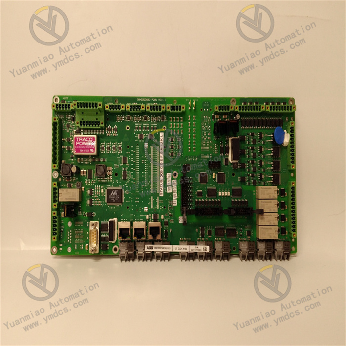
UNITROL 1010 adopts ABB’s proven modular digital‑excitation hardware architecture. Core components include high‑performance multi‑CPU processors, large‑capacity program‑and‑data memory, multi‑channel analog‑acquisition loops (PT/CT signal conditioning, isolation, A/D conversion), digital I/O loops, thyristor‑rectifier‑bridge digital‑firing‑control unit, redundant communication links, power‑management unit, LCD touch‑screen and debugging communication ports. Internal strong‑weak‑electric partitioning and multi‑power‑domain isolation separate CPU core, analog‑measurement loops, firing circuits and communication ports onto independent power domains so that single‑point power‑supply faults will not propagate. Measurement loops integrate high‑precision isolation amplifiers and anti‑aliasing filters to ensure accurate acquisition of generator voltage, current and field‑current signals.
The backplane uses ABB‑standard rack connectors; boards are plugged in via guide rails and backplane interfaces. The front‑panel accommodates the LCD touch‑screen, status LEDs, debugging ports (USB / Ethernet / serial port) and emergency‑control push‑buttons for direct on‑site‑engineer terminal connection. The PCB uses industrial flame‑retardant ruggedized design. All components pass industrial‑temperature‑grade screening and full‑load burn‑in, optimized for long‑term uninterrupted power‑plant‑cabinet operation, strong rectifier‑bridge electromagnetic interference and temperature‑cycle environments. Given UNITROL 1010’s large global installed base, OEM and high‑quality compatible spare parts are critical resources for legacy‑unit maintenance.
4.2 Structural & Engineering Advantages
ABB‑standard modular rack‑mount structure supports flexible configuration and expansion of plug‑in CPU, I/O, power‑supply, communication and firing boards within one control cabinet. Dual‑redundant AVR channels are installed in adjacent rack slots; redundant‑synchronization links use dedicated internal backplane signal traces without extra optical‑fibers or network cables, delivering compact layout and high reliability. Dedicated ABB PCM600 / Composer software unifies controller configuration, parameter tuning, protection‑setting and fault‑oscillography analysis. All application programs, parameters and firmware versions can be backed‑up online; configurations may be restored after board replacement without full on‑site retuning.
Standardized hardware and software architecture reduce maintenance‑staff training costs and spare‑part diversity. For aging UNITROL 1010 installations, spare‑part management and fault‑replacement capability for key CPU, power‑supply and firing boards directly determine whether units can safely operate until the next major overhaul or retrofitting, making them strategic long‑term‑maintenance spare parts for power plants.
5. Working Principle
UNITROL 1010 digital excitation regulator implements closed‑loop excitation‑control workflow: generator voltage/current measurement → multi‑loop digital‑PID/PSS regulation → rectifier‑bridge firing‑angle output → field‑current closed‑loop control → limit‑and‑protection interlock → redundancy & self‑diagnosis fault tolerance, to realize automatic generator‑terminal‑voltage regulation, reactive‑power control and full‑range protection‑limiting functions for synchronous generators.
During operation, the device acquires real‑time signals including generator‑terminal voltage U, stator current I, active power P, reactive power Q, field current If, field voltage Uf and unit frequency f via PT/CT sensors. Under digital‑regulation‑algorithm scheduling, the main CPU executes the AVR main‑regulation loop at millisecond‑level cycles: measured terminal voltage is compared against the set‑point; deviation is processed by PID regulation and lead‑lag compensation to output thyristor‑rectifier‑bridge firing angle α. Optically‑isolated firing pulses are sent to the rectifier cabinet to control DC‑excitation‑voltage output of the three‑phase fully‑controlled rectifier bridge, adjusting generator‑rotor field current If and thereby modifying generator no‑load electromotive force Eq and terminal voltage U to close the regulation loop.
During generator leading‑/lagging‑power‑factor operation, terminal‑voltage deviation, system disturbances or unit anomalies, limiters (OEL/UEL/VHz/stator‑current) and the PSS auxiliary channel intervene automatically according to operating conditions to modify regulation outputs and prevent generator leading‑mode instability, over‑excitation overheating and low‑frequency oscillation. Meanwhile, the regulator uploads operating parameters, status and alarms to plant DCS/SCADA via communication interfaces and receives remote‑set‑point, start‑stop and de‑excitation commands.
Under redundant configuration, primary and standby AVR channels synchronize measured values, regulation outputs and status information in real‑time over high‑speed redundant links to guarantee fully‑consistent channel‑operating states. Upon primary‑channel failure, the standby channel automatically takes over firing‑pulse output within milliseconds for bumpless field‑current transfer. Continuous self‑diagnosis circuits monitor health status of CPU, memory, measurement loops, firing circuits, power supplies and communication links. Alarms are triggered via LCD and HMI upon anomalies. Maintenance personnel may hot‑swap faulty boards online; after system recovery, data is automatically synchronized and redundancy is re‑established.
6. Troubleshooting
6.1 Abnormal generator‑terminal‑voltage fluctuation or large deviation from set‑point
| Probable Cause | Inspection Method | Remedial Action |
|---|---|---|
| Improperly‑tuned AVR‑regulation parameters or PID‑parameter drift | Review AVR‑PID parameters and oscillography traces via commissioning software | Retune PID parameters according to unit model; restore previous controlled‑version parameters |
| PT‑measurement‑loop open‑circuit or poor contact | Compare device‑measured values against local PT secondary‑side voltage | Inspect PT secondary loops, fuses and terminals; tighten or replace faulty components |
| Abnormal rectifier‑bridge firing angle or thyristor failure | Review firing‑angle α, field‑voltage/current oscillography; inspect bridge‑arm fuses | Replace faulty thyristors / fast fuses; troubleshoot firing circuits |
| Abrupt generator‑reactive‑load change or system disturbance | Compare P‑Q‑U oscillography against grid‑disturbance events | Normal dynamic‑response phenomenon; optimize PSS parameters if required |
6.2 Device alarms, AVR‑channel fault or abnormal redundant‑switching
| Probable Cause | Inspection Method | Remedial Action |
|---|---|---|
| Fault in primary AVR‑channel CPU board or measurement loop | Check LCD alarms and event sequence; read diagnostic words via commissioning software | Hot‑swap faulty CPU board per procedure; restore programs and parameters |
| Mismatched firmware‑version or parameter settings between primary‑standby channels | Compare firmware versions and regulation parameters of both channels | Unify firmware and parameters; upgrade sequentially following manufacturer manuals |
| Redundant‑synchronization‑link fault or poor backplane‑connector contact | Observe redundant‑status LEDs and redundancy‑diagnostic information | Inspect backplane connectors; re‑seat channel boards; replace backplane if necessary |
| Faulty device power‑supply module or abnormal power input | Measure dual‑channel device‑supply voltages | Inspect DC‑panel power supplies; replace faulty power‑supply board / module |
6.3 Abnormal field‑forcing / de‑excitation operation or rotor‑overcurrent alarm
| Probable Cause | Inspection Method | Remedial Action |
|---|---|---|
| Unreasonable limiter set‑points or spurious OEL/UEL operation | Review limiter‑action oscillography and setting values | Recalculate and adjust limiter set‑points per generator nameplate and protection standards |
| De‑excitation‑switch failure to operate or spurious tripping | Inspect de‑excitation‑switch operating coils, auxiliary contacts and control loops | Overhaul de‑excitation switch; replace faulty coils / auxiliary contacts |
| Rotor‑loop short‑circuit or ground‑fault | Measure rotor‑insulation resistance and excitation‑loop‑to‑ground resistance | Shut down unit to inspect rotor slip‑rings, carbon brushes and excitation‑loop insulation |
| Rectifier‑bridge runaway or thyristor direct‑conduction | Review rectifier‑bridge output‑voltage waveforms and bridge‑arm status | Shut down unit to inspect thyristors; replace faulty components; verify firing pulses |
6.4 Communication loss or non‑refreshing data between device and plant DCS/SCADA
| Probable Cause | Inspection Method | Remedial Action |
|---|---|---|
| Loose communication cables or damaged interfaces | Check communication‑board LEDs and network / serial‑cable connections | Retighten cables; hot‑swap faulty communication board per procedure |
| Incorrect or conflicting IP‑address / communication‑parameter configuration | Verify device‑communication‑configuration against DCS point‑list and protocol settings | Reconfigure network parameters via commissioning software; resolve IP conflicts |
| Faulty device‑communication board | Cross‑test by swapping communication boards with adjacent channels | Replace faulty communication board; restore communication configuration |