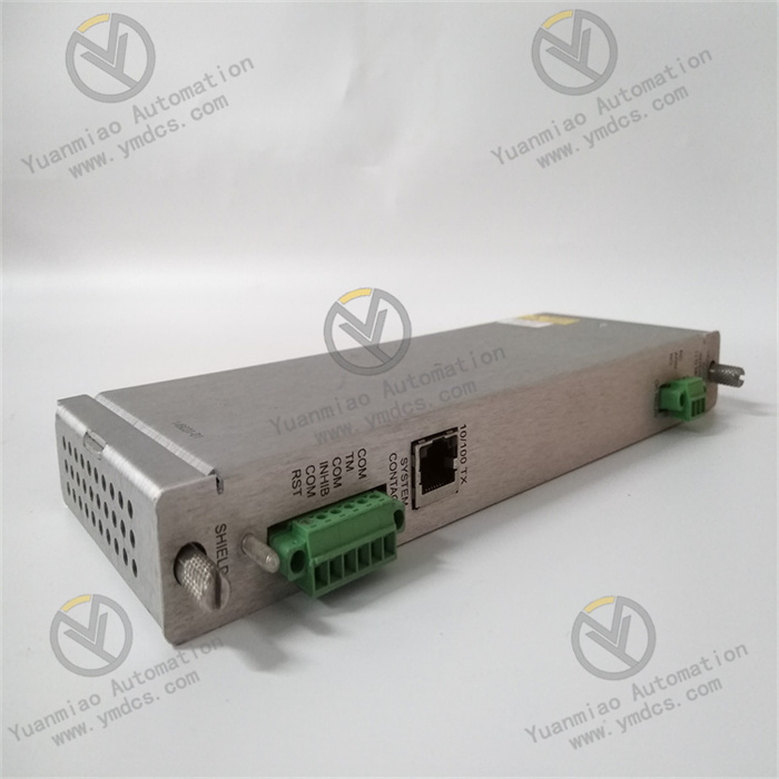
Description
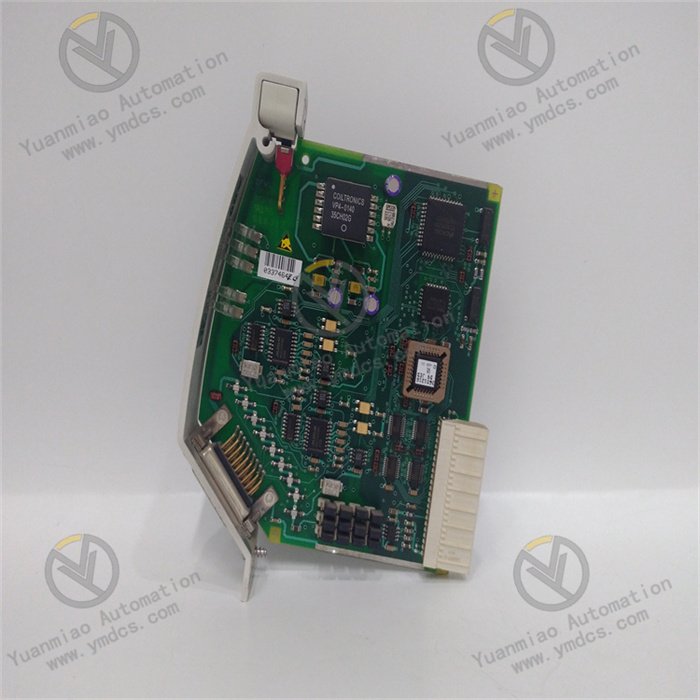
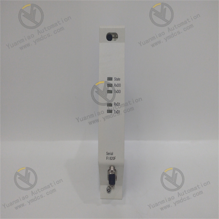
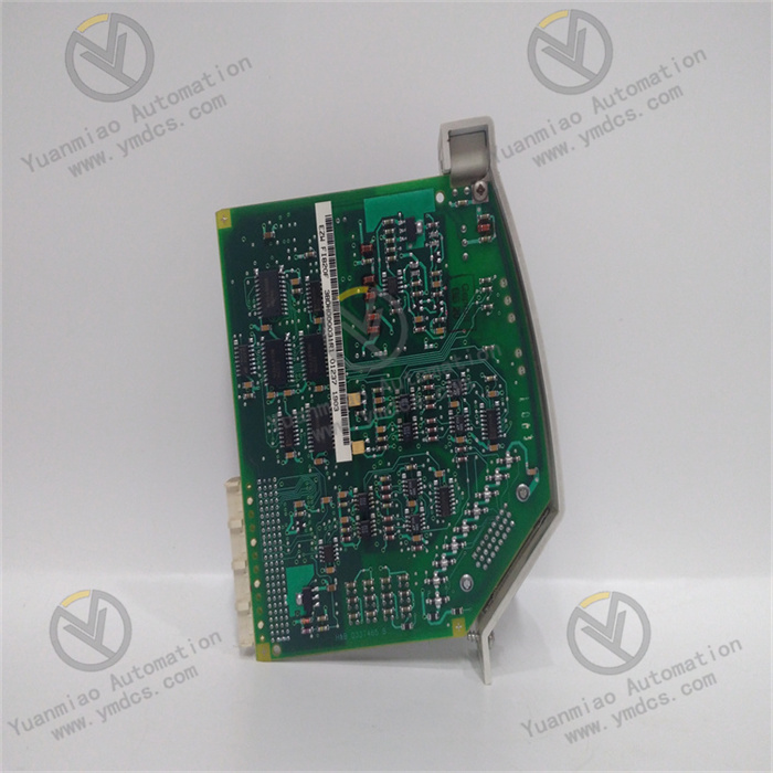
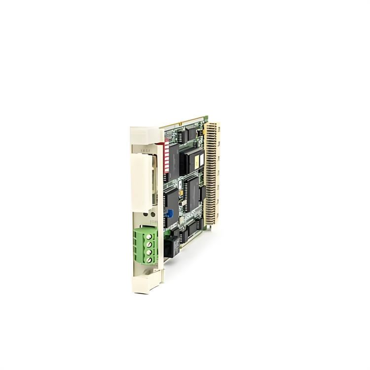
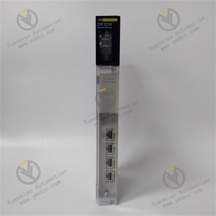
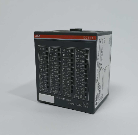
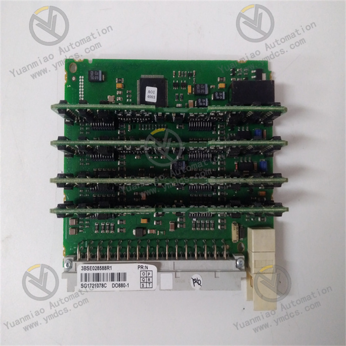
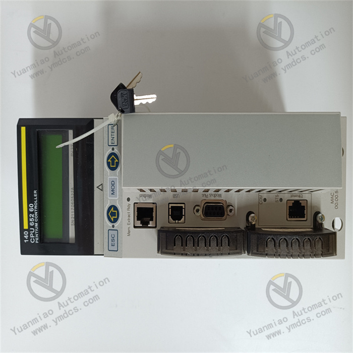
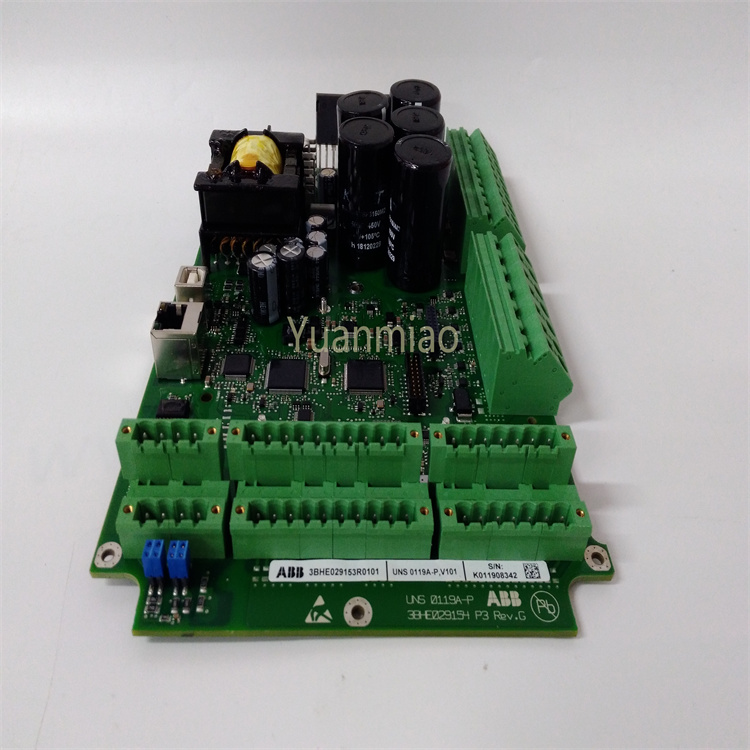
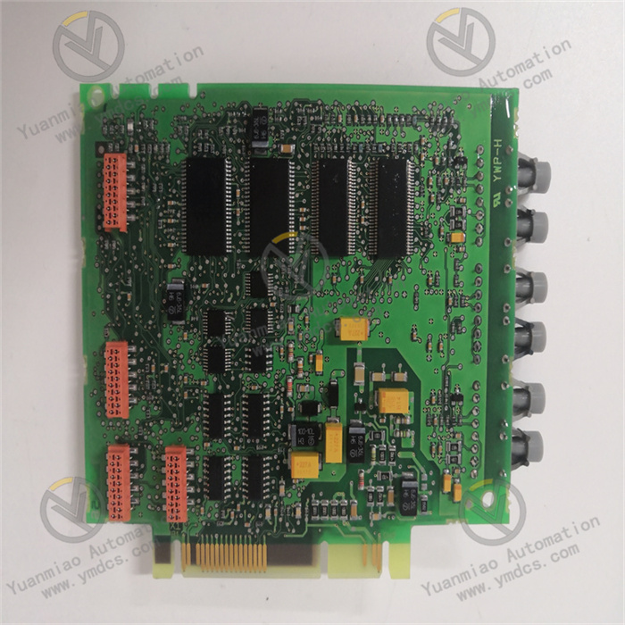
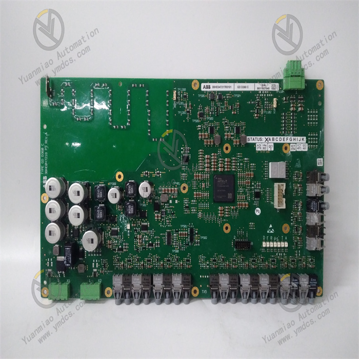
ABB FI820F 3BDH000031R1
Functional Features
- Multiple Interface Types: Provides 2 serial interfaces with physical options of RS485 (half-duplex), RS422 (full-duplex), or RS232, with a maximum configurable transmission rate of 38.4K Baud. The desired physical interface can be easily selected via different connection cables, and all interfaces are electrically isolated to effectively prevent signal interference and electrical faults.
- Redundancy Support: Can be used with redundant AC 800F controllers to achieve redundant operation, enhancing system reliability and availability. This ensures the system remains operational even if a component fails.
- Hot-Swap Function: Allows module removal or insertion during operation without system shutdown, facilitating maintenance and upgrades, reducing downtime, and improving production efficiency.
- Protocol Support: Connects to various serial fieldbuses and protocols. The standard protocol is MODBUS, with support for multiple others such as Profinet, enabling communication and data exchange with other devices across diverse industrial scenarios.
Performance Parameters
- I/O Signals: Features 8 input channels that accept 0–30V DC voltage signals and output 0–20mA DC current signals, meeting the acquisition and control needs of various industrial field signals.
- Operating Temperature Range: -40°C to 70°C, demonstrating strong environmental adaptability to different industrial temperature conditions.
- Dimensions: Approximately 200mm×100mm×50mm, compact for easy installation in various control cabinets or equipment.
- Communication Interfaces: Equipped with multiple interfaces (Ethernet, serial communication, fieldbus) for convenient connection and communication with other devices, systems, and networks.
- Power Requirements: Typically operates at 220V DC, though specifications may vary by application scenario and configuration, requiring confirmation based on actual conditions.
- Application Fields: As a high-performance and reliable serial I/O module designed for harsh industrial environments, it is widely used in data acquisition, monitoring, control, and fault diagnosis for industrial equipment and systems, such as automation control systems in chemical, power, metallurgical, and pharmaceutical industries.
ABB FI820F 3BDH000031R1
This analog input module for industrial automation (commonly used in PLC or DCS systems) primarily collects analog signals (e.g., voltage, current, temperature, pressure) from field devices and converts them into digital signals for processing by control systems. Below is a detailed analysis of its core working principles:
1. Hardware Architecture and Signal Processing Flow
- Signal Input Interface
- 4–20mA current signals (industrial standard)
- 0–10V voltage signals
- Temperature signals from resistance temperature detectors (RTDs) or thermocouples (TCs) (some models require dedicated terminal modules).
- Supported Signal Types: Compatible with multiple analog signals, such as:
- Channel Count: 8 channels ("8" in "FI820F" typically denotes 8 inputs).
- Electrical Isolation: Independent channel isolation to avoid signal interference and improve noise resistance.
- Analog-to-Digital Conversion (A/D Conversion)
- Core Function: Converts analog signals to digital values (binary or hexadecimal) via a built-in analog-to-digital converter (ADC).
- Conversion Accuracy: Resolution is typically 12-bit, 14-bit, or higher (model-dependent); higher precision brings measured values closer to real signals.
- Sampling Rate: Samples input signals at a preset frequency (e.g., hundreds of times per second) to ensure real-time performance.
- Signal Conditioning and Filtering
- Signal Conditioning: Amplifies, attenuates, and linearizes input signals to match the ADC's input range.
Example: A 4–20mA signal may first be converted to a voltage signal (e.g., 1–5V via a 250Ω resistor) before being fed to the ADC. - Anti-Interference Filtering: Suppresses high-frequency noise through hardware filter circuits (e.g., RC filters) or digital filtering algorithms (e.g., average filtering, first-order lag filtering).
- Communication and Data Transmission
- Connection to Control Systems: Transmits digitized signals to the controller (CPU) via bus interfaces (e.g., ABB's CANopen, PROFINET, Modbus).
- Data Format: Data is usually encapsulated in a specific protocol (e.g., SDIO protocol in ABB AC 800M systems), including channel addresses, values, and status flags (e.g., overrange, open circuit).
- Real-Time Performance: Supports periodic data refresh (e.g., every 10ms) to meet industrial control real-time requirements.
2. Key Technical Features
- Self-Diagnosis and Fault Detection
- Channel fault detection: Signal overrange (e.g., >110% of range), open circuit (current <3.6mA), short circuit, etc.
- Module status monitoring: Power failure, overheating, communication anomalies, etc.
- Built-in Diagnostics:
- Fault Signal Output: Fault information is fed back via LED indicators (e.g., "FAULT" light on the module) or status bits in bus messages.
- Calibration and Linearization
- Hardware Calibration: Supports zero and span calibration (e.g., via module buttons or software tools) to ensure measurement accuracy.
- Nonlinear Compensation: Built-in algorithms linearize nonlinear signals from thermocouples or RTDs (e.g., look-up tables, polynomial fitting).
- Power Supply and Isolation Design
- Channel-to-channel isolation: Prevents crosstalk between channels.
- Module-to-system isolation: Protects the control system from field interference.
- Independent Power Supply: Typically powered by the system (e.g., 24VDC); some models support redundant power inputs.
- Electrical Isolation:
3. Typical Application Scenarios
The FI820F module is widely used in industrial scenarios requiring high-precision analog signal acquisition, such as:
- Process Control: Monitoring temperature, pressure, and flow in chemical, petroleum, and metallurgical industries.
- Power Systems: Measuring electrical parameters like voltage, current, and power.
- Mechanical Equipment: Monitoring motor status (e.g., vibration, temperature sensor signals).
- Building Automation: Monitoring environmental parameters (e.g., temperature, humidity, liquid level).
4. Differences from Similar Models
| Feature | FI810F 3BDH000030R1 | FI820F 3BDH000031R1 |
|---|---|---|
| Channel Count | 8 channels | 8 channels |
| Signal Types | Standard voltage/current | May support more (e.g., RTD/TC) |
| Resolution | 12-bit or 14-bit | 14-bit or higher |
| Communication Protocols | Specific buses (e.g., CANopen) | Advanced protocols (e.g., PROFINET) |
| Diagnostics | Basic fault detection | Enhanced self-diagnostics (e.g., channel-level fault location) |
| Applications | General analog acquisition | High-precision/complex signals (e.g., temperature) |
Common Faults and Solutions for ABB FI820F 3BDH000031R1
1. Module Communication Failures
- Symptoms:
- Module cannot communicate with the control system (e.g., PLC/DCS), with abnormal indicator lights (e.g., communication light off or flickering).
- System errors like "module lost" or "communication timeout."
- Possible Causes and Solutions:
- Power Issues:
- Cause: Unstable power supply, loose power cables, or faulty power modules.
- Solution: Check power input (≈24VDC) against module specifications using a multimeter. Reconnect power terminals and test with a spare power module.
- Communication Line Faults:
- Cause: Damaged cables, loose terminals, poor grounding, or interference.
- Solution: Inspect cables (e.g., PROFIBUS, Modbus) for damage and measure signal waveforms with an oscilloscope. Re-tighten terminals, ensure shielded grounding, and replace cables or use backup channels.
- Incorrect Address Settings:
- Cause: Mismatch between physical module address (e.g., DIP switch) and system configuration.
- Solution: Confirm address settings (e.g., DIP switch position) match the control system configuration. Check module parameters in engineering files for software-configured addresses.
- Module Firmware Issues:
- Cause: Outdated or corrupted firmware leading to protocol incompatibility.
- Solution: Update firmware to the latest stable version via ABB tools (e.g., Control Builder). If issues persist, restore factory settings (backup configurations first).
2. Abnormal Input Signals
- Symptoms:
- Input signals are not correctly acquired (e.g., no response from module indicators or system when field digital signals change).
- False signal triggers (e.g., system shows signals with no input).
- Possible Causes and Solutions:
- Mismatched Signal Types:
- Cause: Module-supported signal types (e.g., dry/wet contacts, voltage/current) do not match field devices.
- Solution: Refer to the module manual to confirm input types (e.g., FI820F is typically an 8-channel digital input module). Verify field device signals meet module requirements (e.g., dry contacts need external power; wet contacts need module power).
- Incorrect Wiring or Poor Contact:
- Cause: Reversed signal wires, loose terminals, or poor connections.
- Solution: Check signal wire polarity and channel mapping against the module’s wiring diagram. Use a multimeter to test field signals (e.g., resistance for switches, voltage levels). Re-crimp terminals or replace wiring for secure connections.
- Signal Interference:
- Cause: Parallel routing of high-power and signal cables, or high-frequency interference sources (e.g., motors, inverters).
- Solution: Separate signal and power cables by ≥30cm, use shielded twisted-pair cables with proper grounding. Install filter capacitors or signal isolators (e.g., isolated transmitters) at module inputs.
- Damaged Channels:
- Cause: Overvoltage, surges, or frequent switching damaging internal circuits.
- Solution: Switch to backup channels. If all channels fail, the module may have hardware faults requiring repair or replacement.
3. Hardware Failures (Physical Damage)
- Symptoms:
- Abnormal heat, smoke, or odor from the module casing.
- Abnormal indicator lights (e.g., all lights constant on/off or chaotic flickering).
- Possible Causes and Solutions:
- Overvoltage/Overcurrent Surges:
- Cause: Short circuits in field devices, lightning surges, or wiring errors burning internal components.
- Solution: Power off immediately and check for short circuits in field equipment and wiring. Ensure external circuits are fault-free before replacing the module (consider surge protectors).
- Mechanical Damage:
- Cause: Loose installation or excessive vibration causing internal component detachment or connector damage.
- Solution: Check module mounting and rail clips for tightness. Repair or replace modules with bent/fractured connector pins.
4. System Compatibility Issues
- Symptoms:
- Functional anomalies or unrecognized modules due to software version mismatches with the control system.
- Possible Causes and Solutions:
- Incorrect Software Configuration:
- Cause: Module type or parameters (e.g., input filter time, signal type) not properly configured in engineering files.
- Solution: Re-import module GSD files (e.g., for PROFIBUS) to ensure configuration matches hardware. Check input channel parameters (e.g., excessive filter time may delay signals).


