Description
1. Overview
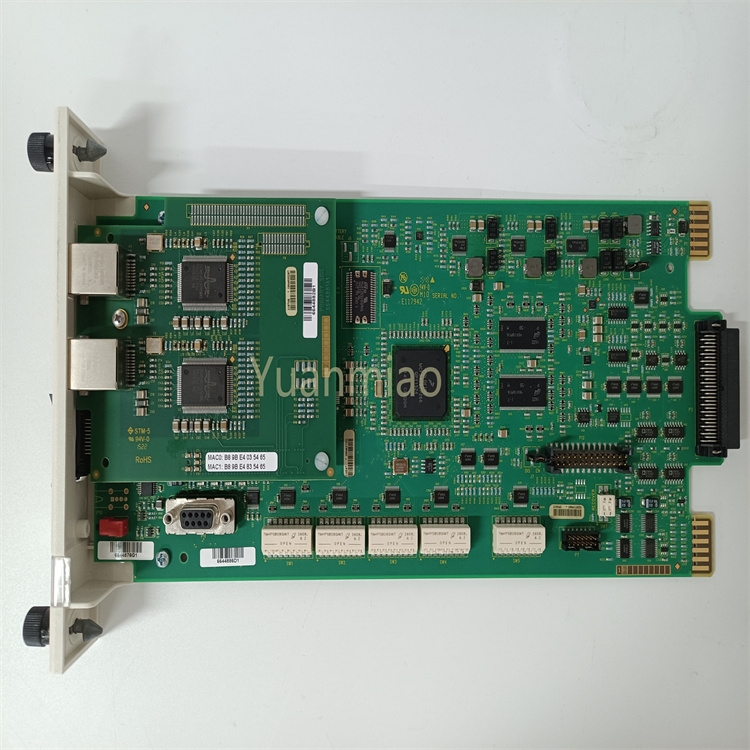
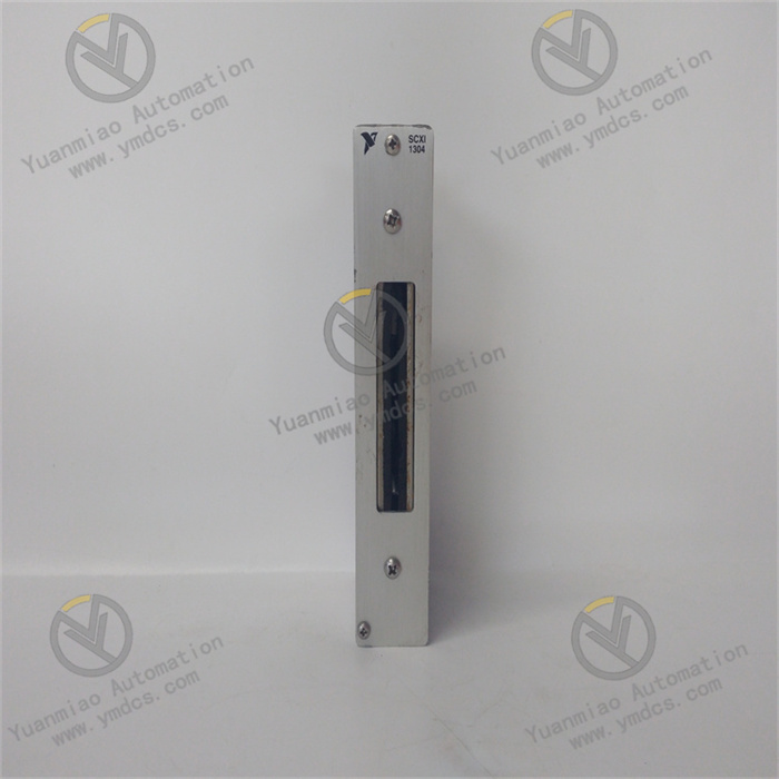
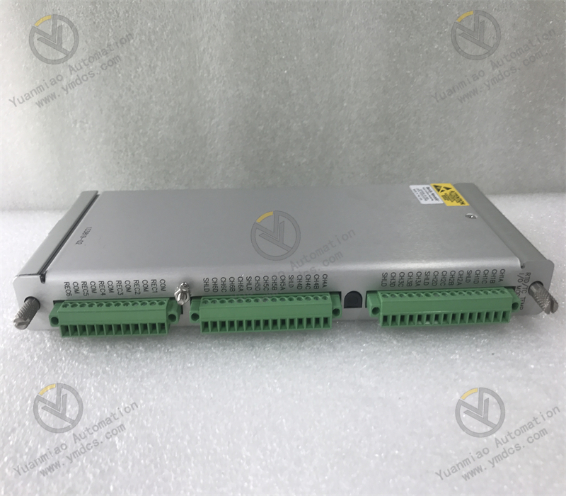
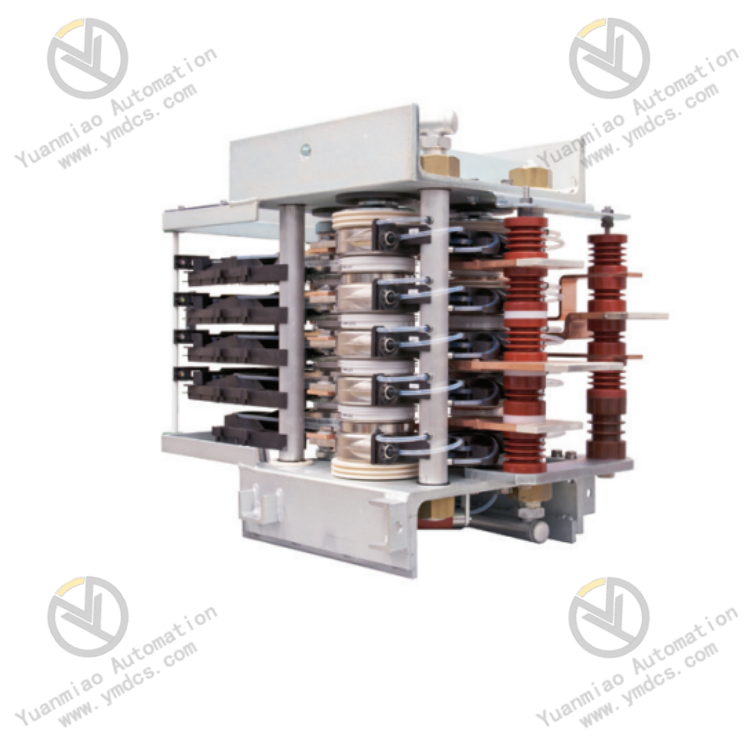
ABB S‑123H (part number 3BHB030479R0512) is an original rectifier phase‑detection module for ACS6000 medium‑voltage variable‑frequency drives. It serves as the core signal acquisition and synchronization control component for the rectifier unit of medium‑voltage variable‑frequency systems. It is widely deployed in ACS6000 medium‑voltage variable‑speed drive systems for heavy‑duty equipment such as large‑scale medium‑voltage fans, water pumps, compressors and belt conveyors in metallurgy, power generation, chemical, cement and oil‑gas industries.
Designed specifically for rectifier synchronization logic of medium‑voltage variable‑frequency drives, this module detects three‑phase grid voltage phase sequence, voltage amplitude and zero‑crossing phase signals in real time. It provides high‑precision reference phase signals for thyristor firing of the drive rectifier bridge, system synchronous grid‑connection and rectifier logic computation. Manufactured in compliance with ABB industrial variable‑frequency design standards, it features high phase‑acquisition accuracy, fast response, strong anti‑interference capability, high operational stability and wide‑temperature adaptability. It continuously monitors input‑side grid anomalies and cooperates with the main controller to implement fault protection for over‑voltage, under‑voltage, wrong phase sequence and phase loss. As a critical module ensuring smooth start‑up, stable speed regulation and safety interlock protection of ACS6000 medium‑voltage drives, it is suitable for 7×24‑hour non‑stop heavy‑duty industrial operation.
2. Functions and Features
2.1 Core Functions
High‑precision three‑phase phase synchronization detection: Collects three‑phase medium‑voltage grid voltage signals at the drive input side, accurately captures voltage zero‑crossing points and phase offsets, and outputs standard synchronization reference signals. It delivers precise phase references for thyristor firing timing, rectifier waveform shaping and system synchronous operation of the rectifier unit, ensuring well‑regulated rectifier waveforms and controllable harmonics.
Grid phase‑sequence and phase‑loss monitoring: Performs automatic three‑phase phase‑sequence identification and phase‑loss fault judgment. It accurately detects positive phase sequence, reverse phase sequence and single/two‑phase phase‑loss anomalies, identifies grid‑side faults in advance and prohibits abnormal drive start‑up, thus preventing rectifier module damage and equipment tripping caused by incorrect phase sequence.
Grid‑voltage anomaly monitoring and protection: Monitors input‑side grid conditions including over‑voltage, under‑voltage, voltage fluctuation and three‑phase unbalance in real time. It uploads grid parameters to the drive main control system and supports multi‑level alarm, load reduction and emergency shutdown protection logic to safeguard the variable‑frequency drive and downstream motor equipment.
Coordinated calibration of rectifier firing logic: Tracks dynamic changes of grid phase and rectifies rectifier firing angles on‑the‑fly to accommodate grid voltage fluctuations and load transients. It suppresses rectifier waveform distortion and current surges, and mitigates grid impact and equipment vibration during drive start‑up and load variation.
Full‑link self‑diagnosis and fault alarming: Built‑in hardware self‑diagnosis identifies module power supply anomalies, sampling‑loop faults, signal disconnection, chip malfunctions and communication failures. Fault codes are reported to avoid loss‑of‑synchronization of rectification and system runaway risks resulting from module failure.
Industrial‑grade real‑time data interaction: Performs high‑speed data exchange with the ACS6000 drive main control unit. Phase parameters, grid‑voltage values, fault status and operating conditions are uploaded for system trend logging, fault tracing, parameter analysis and maintenance diagnostics.
Long‑term stable adaptability for harsh conditions: Adapted to medium‑voltage drive cabinet environments with high temperature, dust, strong electromagnetic interference and frequent load swings. It maintains stable rectifier synchronization logic and prevents drive tripping and rectifier module burnout induced by phase drift or loss of synchronization.
2.2 Product Features
Ultra‑high phase‑acquisition accuracy: Equipped with high‑precision voltage‑sampling and phase‑demodulation circuits with minimal phase‑detection error. It captures subtle grid phase offsets and voltage fluctuations, meeting process requirements for high‑precision rectification and low‑harmonic operation of medium‑voltage variable‑frequency drives.
Strong electromagnetic interference immunity: Optimized for intense electromagnetic fields and high‑frequency harmonic interference in medium‑voltage variable‑frequency systems. Multi‑stage isolation‑filtering and electromagnetic shielding resist high‑frequency noise from rectifier and inverter circuits and prevent signal distortion and false phase judgment.
Stable wide‑temperature performance: Industrial‑grade wide‑temperature components deliver ultra‑low temperature drift. Accuracy and synchronization logic remain consistent under cabinet temperature cycling without parameter drift or functional failure.
Compact modular construction: Standard embedded form factor fits ACS6000 drive cabinet layout with small footprint. Easy disassembly and assembly support on‑line maintenance and spare‑part replacement without equipment shutdown for high serviceability.
Anti‑corrosive conformal coating: PCB is protected with industrial conformal coating against moisture, dust, salt spray and corrosion. Service life is extended for harsh environments in chemical, metallurgical and mining sites.
Fast fault‑response mechanism: Millisecond‑level fault identification and signal output. Protection actions are triggered rapidly upon grid anomalies to minimize equipment damage.
High interchangeability without recalibration: Factory‑calibrated for full compatibility of identical part numbers. Replacement requires no complex phase calibration or parameter tuning for plug‑and‑play deployment in new‑unit assembly, aged‑module replacement and system technical retrofits.
3. Specifications
| Item | Technical Specification |
|---|---|
| Model | S‑123H |
| Part Number | 3BHB030479R0512 |
| Device Type | Rectifier Phase‑Detection Module for ACS6000 Medium‑Voltage Variable‑Frequency Drive |
| Manufacturer | ABB (Switzerland) |
| Applicable Equipment | ABB ACS6000 Series Medium‑Voltage AC Variable‑Frequency Drives |
| Core Functions | Three‑phase grid phase detection, zero‑crossing synchronization, phase‑sequence monitoring, grid anomaly protection, rectifier logic calibration |
| Applicable Grid Voltage | 6.0kV~6.9kV medium‑voltage industrial power grid |
| Operating Supply | 24VDC industrial control power |
| Detection Response Time | ≤10 ms fast fault response |
| Phase Acquisition Accuracy | Industrial high‑precision grade, negligible phase drift |
| Operating Temperature | -40℃~+85℃ |
| Storage Temperature | -45℃~+90℃ |
| Ambient Humidity | 5%~95%RH, non‑condensing |
| Protection Class | IP20 (cabinet‑mounted module) |
| Communication Interface | Internal high‑speed drive bus, real‑time data synchronization with main control unit |
| Protection Process | PCB conformal coating: moisture‑proof, dust‑proof and corrosion‑resistant |
| Operational Characteristics | High‑precision phase detection, fast response, high anti‑interference, wide‑temperature stability, self‑diagnosis protection, high interchangeability |
4. Working Principle
The ABB S‑123H 3BHB030479R0512 phase module operates based on three‑phase voltage sampling, zero‑crossing phase demodulation and real‑time logic judgment. As the phase‑reference core of the ACS6000 medium‑voltage drive rectifier system, it delivers accurate signal support for drive rectifier firing, synchronous operation and grid protection.
During standby and running states, the module samples three‑phase medium‑voltage grid voltage signals through dedicated sampling loops. After isolation step‑down, multi‑stage filtering and waveform shaping, grid harmonics, electromagnetic interference and voltage noise are suppressed to restore standard sinusoidal waveforms. Internal high‑speed demodulation chips precisely capture zero‑crossing instants of each phase, calculate three‑phase phase angles, phase differences and phase‑sequence logic, and transmit standardized synchronization reference signals to the drive main control unit.
Based on precise phase signals from the module, the main control unit dynamically calculates optimal thyristor firing angles for the rectifier bridge to achieve accurate controllable‑rectifier waveform control. It ensures smooth commutation, continuous current and qualified harmonic suppression of the rectifier unit. Meanwhile, the module continuously monitors three‑phase voltage amplitude balance, phase‑sequence status and voltage fluctuation range. In case of phase loss, reverse phase sequence, over‑voltage, under‑voltage or three‑phase unbalance, fault signals are output within milliseconds to activate drive alarming, start‑up interlock and emergency shutdown protection logic, preventing damage to rectifier modules, inverter modules and motors caused by grid abnormalities.
Hardware self‑diagnosis continuously monitors module power supply, sampling circuits and chip status. Upon board‑level faults, wiring disconnection or signal anomalies, fault codes are reported and system status is latched. This prevents severe failures including rectifier loss‑of‑sync, system runaway and hardware burnout, and guarantees long‑term reliable operation of the medium‑voltage variable‑frequency system.
5. Application Scenarios
ACS6000 medium‑voltage drive matching: Exclusively for full series ABB ACS6000 medium‑voltage drives. It provides core phase‑reference signals for normal start‑up, rectifier synchronization, steady‑state speed regulation and load adjustment, and constitutes an essential functional module for medium‑voltage variable‑frequency systems.
Heavy‑duty variable‑speed drive systems: Widely used for high‑power medium‑voltage variable‑frequency equipment in metallurgical rolling, mine hoisting, chemical conveying, thermal‑power fans & water pumps and cement industries. It ensures stable rectifier logic and shock‑free operation under heavy‑duty conditions.
Grid anomaly monitoring and equipment protection: Deployed at industrial sites with frequent grid fluctuations and violent load variations. It gives early warning of grid hazards and avoids production outages and equipment damage caused by phase loss or wrong phase sequence.
Retrofit and replacement of legacy variable‑frequency systems: For aged ACS6000 drives suffering from phase‑module aging, phase drift, measurement inaccuracy and recurring alarms. System logic and cabling remain unchanged while rectifier synchronization and protection functions are rapidly restored.
Long‑term monitoring in harsh industrial environments: Wide‑temperature tolerance, conformal coating and high noise immunity adapt to medium‑voltage drive cabinets with high temperature, high humidity, heavy dust and strong electromagnetic interference, meeting requirements for 7×24‑hour continuous monitoring.
New‑unit assembly and system expansion & commissioning: Supports new medium‑voltage drive assembly, measurement‑point expansion for legacy equipment and technical retrofit commissioning. Standardized parameters ensure consistent system logic, convenient commissioning and high stability.
6. Common Faults and Troubleshooting
6.1 Drive reports phase anomaly / synchronization failure
Causes: Drift or accuracy degradation of module phase‑sampling circuits; loose or poor‑contact three‑phase sampling wiring; distorted grid voltage with excessive harmonics; aged module yielding inaccurate synchronization signals; board‑level parameter offset.
Remedy: Inspect and tighten terminals of three‑phase sampling loops, clean oxide and dust; check grid voltage waveform and harmonic content to eliminate grid‑side defects; restart drive to reset synchronization logic; calibrate module phase‑sampling parameters; replace original module if faults persist.
6.2 Wrong‑phase‑sequence alarm, frequent lock‑out preventing start‑up
Causes: Actual grid phase‑sequence change on‑site; incorrect phase‑sequence of sampling wiring; malfunction of module phase‑sequence identification circuit; false logic judgment due to electromagnetic interference.
Remedy: Verify actual grid phase sequence and confirm whether grid re‑phasing has occurred; check sampling wiring phase sequence and correct mis‑wiring; locate interference sources and optimize shielding & earthing; replace spare module if false alarms continue with correct grid phase sequence.
6.3 False over‑voltage / under‑voltage alarms under normal grid voltage
Causes: Drift or accuracy failure of module voltage‑sampling circuits; filter anomaly and noise coupling in sampling loops; parameter offset caused by long‑term high‑temperature operation; sampling‑voltage fluctuation from loose connections.
Remedy: Measure actual three‑phase grid voltage to confirm normal grid conditions; tighten sampling terminals and improve cable shielding; enhance cabinet cooling to reduce board operating temperature; recalibrate voltage‑sampling thresholds; replace module if false alarms recur.
6.4 Module off‑line, communication interruption, no phase‑signal output
Causes: Abnormal or lost 24VDC module supply; oxidized board gold‑fingers and poor slot contact; damage to internal core chips or sampling circuits; internal bus‑link failure.
Remedy: Measure module supply voltage and troubleshoot power loops; power off, extract module, clean gold‑fingers and slot oxidation, then reinstall firmly; check internal drive bus status; replace module directly if hardware links are intact yet no output exists.
6.5 Distorted operating waveforms and large current fluctuations
Causes: Module phase‑detection drift leading to incorrect rectifier firing angles; distorted sampling signals and disordered synchronization logic; degraded anti‑interference performance of board; failed loop filtering.
Remedy: Observe drive rectifier output waveforms and operating current to confirm distortion; eliminate wiring‑interference and earthing defects; reset system synchronization parameters; improve cabinet electromagnetic environment; replace module if waveform anomalies cannot be repaired.
6.6 Module high‑temperature alarm and intermittent malfunctions
Causes: Blocked cabinet air duct and insufficient heat dissipation; accumulated heat from long‑term full‑load operation; aging board circuits with abnormal power consumption; excessive cabinet ambient temperature.
Remedy: Clean cabinet dust filters and air ducts to improve ventilation; lower cabinet ambient temperature; inspect module operating conditions for circuit anomalies; replace original module if high‑temperature alarms and intermittent faults occur repeatedly.