Description
1. Product Overview
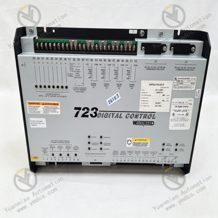
Model: 8280-501
Brand: Woodward
Product Name: Series 723 High-Performance Digital Governor Controller for Generators & Turbines
Product Positioning: Industrial-grade core digital governor control equipment designed for reciprocating engines, gas turbines and small steam turbines. It is a dedicated intelligent controller for speed, load and fuel regulation of generator sets, widely adopted for precise speed control and paralleling applications of industrial power units.
Core Functions: Realize closed-loop control of unit start/stop, speed ramp-up/ramp-down and steady-state speed regulation. Support unit paralleling, load sharing, droop control and isochronous control. Integrated protection logics including fuel limit and inlet air pressure limit. It precisely manages unit operating conditions to prevent overspeed, overload, instability and other faults, ensuring continuous, stable and safe operation of power units.
Applicable Equipment: Diesel generator sets, gas generator sets, small gas turbines, industrial steam turbines and reciprocating power units.
Application Scenarios: Harsh industrial power control scenarios including captive power plants, oilfield power equipment, factory standby power generation systems, metallurgical power units and offshore platform power systems. Suitable for installation in unit control cabinets and local control boxes.
2. Technical Features
- High-Precision Digital Speed Governing Adopts fully digital closed-loop control algorithm featuring high speed control accuracy and fast dynamic response. It precisely accommodates variable load and variable operating conditions, effectively suppresses speed fluctuation, maintains steady-state stability and meets stringent control requirements for grid-connected power generation and isolated power supply.
- Integrated Multi-Function Unit Control Logic Natively integrates core functions such as isochronous load sharing, droop governing, start-stop sequence control, fuel limit, boost air limit and acceleration/deceleration ramp limit. No external auxiliary control modules required; capable of full automatic unit control independently.
- Wide-Band Speed Signal Compatibility Supports multiple speed acquisition methods including magnetic pickup sensors and proximity switches. Wide input frequency range for speed signals delivers strong compatibility with power units of various types and speed ratings.
- Industrial-Grade Highly Reliable Hardware Design Full metal sealed enclosure with excellent shock resistance, dust resistance and temperature variation tolerance. Withstands electromagnetic interference and temperature/humidity fluctuations on industrial sites and supports 7×24 hours continuous long-term operation under severe working conditions. Built-in comprehensive self-diagnosis function to monitor hardware status and operational faults in real time.
- Convenient Human-Machine Interaction & Parameter Configuration Equipped with a 2-line × 24-character LCD and keypad panel with menu-based visual operation. Supports on-site parameter modification, real-time operating status viewing, fault code retrieval and parameter calibration for simple and efficient maintenance.
- Flexible Actuator Compatibility Compatible with single-stage / dual-stage split actuators and electro-hydraulic servo actuators. Supports single-acting and double-acting control modes, applicable to various power regulating mechanisms such as fuel valves and steam inlet valves for unit retrofits and new installations.
- Comprehensive Unit Protection Mechanism Integrates multiple protection logics including overspeed protection, under-speed protection, overload protection, start timeout and abnormal pressure protection. Automatically locks operating status and outputs protection commands upon fault triggering to avoid unit damage and shutdown accidents and improve operational safety.
3. Specification Parameters
| Item | Parameter |
|---|---|
| Model | 8280-501 (Woodward Series 723) |
| Device Type | Digital Unit Governor / Load Controller |
| Power Supply | DC 18~40V (Rated 24V/32V); Optional DC 90~150V (Rated 125V) |
| Rated Power Consumption | 40W |
| Speed Input Frequency | 400~15000Hz (Magnetic Pickup Sensor) |
| Control Modes | Isochronous Control, Droop Control, Load Sharing, Remote/Local Speed Regulation |
| Display Interface | 2-line × 24-character LCD, menu operation |
| Operating Temperature | -10℃~70℃ |
| Storage Temperature | -20℃~105℃ |
| Ambient Humidity | 5%~95%, non-condensing |
| Compatible Actuators | Single/Dual-Stage Servo Actuators, Electro-Hydraulic Actuators, Fuel Regulating Actuators |
| Overall Dimensions | 320mm × 240mm × 120mm |
| Unit Weight | Approx. 5kg |
| Origin | Original Made in USA |
| Applicable Equipment | Diesel/Gas Generator Sets, Gas Turbines, Small Steam Turbines |
4. Working Principle
- Signal Acquisition & Verification After power-on initialization, the controller continuously collects signals from unit speed sensors, inlet pressure sensors, actuator position feedback, as well as external start/stop and load regulation commands. All acquired signals are filtered, verified and denoised to eliminate interference and provide reliable data for accurate governing calculation. Meanwhile, hardware self-diagnosis is activated to monitor the controller’s operating status in real time.
- Closed-Loop Governing Calculation Built-in PID control algorithm continuously compares the actual unit speed against set speed and dynamically calculates adjustment output according to speed deviation. Output commands are corrected subject to constraints of acceleration/deceleration ramp limits, fuel limits and boost pressure limits to prevent overshoot, runaway and engine stall, realizing precise steady-state speed control.
- Load Control & Paralleling Load Sharing When the unit operates in parallel with grid, the controller can switch to load control mode and support isochronous load sharing and droop load regulation for multiple units. It automatically distributes output power of each unit according to total system load demand, balances load distribution among units, avoids overload and uneven loading of individual units and ensures stable operation of the paralleled system.
- Actuator Drive Regulation Calculated regulation commands are converted into drive signals to precisely adjust the opening of regulating mechanisms such as fuel valves and steam inlet valves. The air intake and fuel supply of the unit are adjusted in real time to dynamically match speed and load requirements and achieve adaptive regulation under varying working conditions.
- Fault Monitoring & Protection Interlock During operation, the controller continuously monitors abnormal speed, actuator faults, signal loss, overtemperature, overload and other fault conditions. Once protection thresholds are reached, outputs are immediately locked and regulating commands cut off. Fault codes are recorded and alarm signals triggered. Cooperating with unit interlock systems, it enables safe shutdown or operating condition protection to prevent equipment damage.
5. Common Faults and Troubleshooting
- Phenomenon: No display after power-on; controller fails to start Possible Causes ① Abnormal external supply voltage, open circuit in power loop or blown fuse; ② Aging or damaged internal power module of the controller; ③ Loose and poorly contacted power terminal blocks. Troubleshooting Cut off power and verify DC 18–40V supply voltage; tighten power terminals and check circuit breakers and wiring; inspect fuses – never short blown fuses. If no response is obtained with normal power supply, the power module is faulty and requires repair or equipment replacement.
- Phenomenon: Severe unit speed fluctuation, unstable governing and excessive steady-state deviation Possible Causes ① Aging speed sensor, signal attenuation or abnormal installation gap; ② Improper PID parameter tuning; mismatched gain and integral parameters for unit operating conditions; ③ Sticking actuator or abnormal feedback signal; ④ Signal distortion caused by on-site electromagnetic interference. Troubleshooting Check installation gap and wiring of speed sensor, clean sensor probe and replace aged sensors; re-tune PID governing parameters to match unit load characteristics; inspect actuator operation and troubleshoot sticking and feedback faults; implement shielding and earthing for signal cables to eliminate electromagnetic interference.
- Phenomenon: Failed paralleling, uneven load distribution after paralleling Possible Causes ① Inconsistent speed reference parameters among units; ② Incorrect configuration of load sharing and droop control parameters; ③ Abnormal communication synchronization between multiple units; ④ Slow governing response of individual unit. Troubleshooting Unify speed reference and droop coefficient parameters of all units and enable load sharing function; verify paralleling synchronization parameters and calibrate unit governing response speed; inspect communication wiring between units to ensure data synchronization; fine-tune load sharing thresholds to achieve balanced loading.
- Phenomenon: Overspeed/under-speed protection tripping during unit start and stop Possible Causes ① Over-fast or slow ramp rate parameters for start-stop; ② Improper fuel/inlet limit parameters; ③ Instantaneous loss or abnormal fluctuation of speed signal; ④ Deviated protection threshold setting. Troubleshooting Optimize start-stop ramp parameters to match unit mechanical response characteristics; reasonably adjust fuel and inlet limit parameters to avoid abrupt energy supply change; inspect speed signal wiring to eliminate transient disconnection and interference; recalibrate overspeed and under-speed protection thresholds according to unit rated conditions.
- Phenomenon: Panel parameters cannot be saved; parameters lost after power cycle Possible Causes ① Abnormal storage chip inside controller; ② Parameter saving operation not completed; ③ Abnormal device firmware. Troubleshooting Strictly execute save confirmation after parameter modification; restore factory settings, re-enter and save unit parameters. If the fault persists, the storage module is defective and requires repair or controller replacement.
- Phenomenon: Frequent signal fault alarms and sensor abnormality alerts during operation Possible Causes ① Damaged sensor wiring, loose connections or poor earthing; ② Sensor performance degradation and accuracy drift; ③ Faulty signal acquisition circuit inside the controller. Troubleshooting Fully inspect wiring of speed and pressure sensors, repair damaged cables, tighten terminals and standardize earthing; measure resistance and output signals of sensors and replace degraded sensors. If alarms remain normal sensors and wiring, the controller acquisition circuit is faulty and requires factory repair.