Description
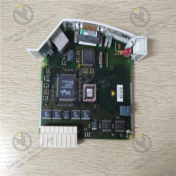
ABB 3BHE0141335R0011
I. Basic Information
Part Number: 3BHE0141335R0011Internal Hardware Model: UAD149A0011Brand: ABBProduct Line: Dedicated I/O signal interface board for UNITROL 5000/6000 static excitation systems of synchronous generators, serving as auxiliary signal interaction unit for excitation regulation channels, cooperating with COB main control board and rectifier trigger board to complete digital signal collection, interlock output and fault signal forwarding of excitation system.
Product Positioning
3BHE0141335R0011 is a dual-channel extended digital I/O card for excitation systems. It completes isolated collection and drive output of interlock signals inside and outside excitation cabinet, de-excitation switch, excitation start-up loop, cooling fan status, rotor earth fault protection and ETS shutdown signals. Full-channel electrical isolation design eliminates harmonic and transient high voltage interference from excitation power loop, ensuring accurate transmission of AVR voltage regulation, PSS stabilizer and excitation limit logic signals. It acts as the core signal transfer hardware spare part for thermal, hydro and gas turbine units to realize local interlock and remote DCS interaction of excitation systems.
Hardware Architecture
Integrated plug-in structure with thickened FR4 flame-retardant PCB, divided into four areas on board: power conversion zone, optocoupler isolated acquisition zone, relay output drive zone and backplane bus interaction zone.
- Power Conversion Unit: Powered by 24VDC backplane bus of excitation cabinet, built-in reverse polarity protection and self-recovery overcurrent fuse, multi-channel linear regulated power supply independently for acquisition chip and relay.
- Digital Input Acquisition Circuit: Each channel equipped with independent high-speed optocoupler isolation, compatible with passive dry contact and 24VDC active signal input; filter circuit eliminates long-line electromagnetic clutter on site.
- Digital Output Drive Circuit: Small power passive relay output, RC absorption circuit on contacts to suppress reverse spike voltage generated by disconnection of inductive loads.
- High-Speed Backplane Bus Interface: Standard multi-pin European connector, realizes two-way real-time data interaction with main control board through cabinet internal parallel bus, built-in hardware channel fault latch circuit.The whole PCB is coated with three-proof insulation coating, all signal ports integrated with ESD and EFT surge protection, adapting to strong electromagnetic and dusty environments in generator rooms.
Mounting Specification
Standard vertical slot direct plug-in installation for UNITROL series metal excitation cabinets, supporting mixed layout of single-channel and dual-channel redundant excitation systems, snap-lock structure on both sides of the card for tool-free disassembly and assembly.It has passed IEC 60068 anti-vibration, humidity cycle and wide-temperature aging reliability tests. Separate front and rear wiring channels physically separate strong and weak current terminals to avoid cable crosstalk.Overall Dimension (L×W×T): 340mm × 118mm × 22mm, net weight 0.23kg.
Compatible Systems
- Excitation Host Platform: UNITROL 5000, UNITROL 6000 self-shunt static excitation regulators
- Matching Core Boards: COB main control board, MUB terminal measurement board, 3BHE014026 series rectifier trigger interface board
- Upper Monitoring System: ABB 800xA DCS, local power station HMI, remote SCADA dispatching system
- External Primary Equipment: De-excitation switch, excitation start-up contactor, rectifier cabinet cooling fan, rotor earth fault protection device, unit ETS trip circuit
- Commissioning Tool: Excitation Master debugging software, supporting channel forcing, fault log reading and online verification of interlock logic
Product Characteristics
- Large-capacity integrated I/O channels, single card concentrates all interlock signal processing of excitation, reducing the number of cards in cabinet and simplifying secondary wiring;
- Independent optocoupler electrical isolation for all channels, complete separation of strong and weak currents, blocking signal distortion and misoperation caused by rectifier bridge harmonics and bus transient voltage;
- Built-in real-time hardware self-diagnosis, full-channel self-test after power-on, continuous monitoring of open circuit, short circuit, undervoltage and relay contact fault during operation, millisecond-level fault code latching;
- Sufficient capacity of passive relay output contacts, can directly drive on-site sound-light alarm and trip intermediate relays without extra signal amplification adapter;
- Adapt to dual-channel redundant excitation architecture, independent signal collection of main and standby channels without mutual interference, fault of single card will not affect operation of another regulation channel;
- Wide temperature and wide voltage industrial adaptation, stable long-term continuous operation in sealed excitation cabinets without air conditioning, three-proof coating resists damp and slight oil & gas corrosion;
- Standardized backplane bus protocol, fully compatible hardware pins of UAD149A series cards, spare part replacement without modifying cabinet wiring and program logic.
II. Technical Specifications
2.1 Electrical Signal Parameters
- Rated Backplane Power Supply: DC24V, tolerance DC20.4V~28.8V, built-in 2A self-recovery fuse
- Typical Power Consumption: 0.45W, max full-load power consumption 0.75W
- Digital Input DI: 16-channel isolated optocoupler input, compatible with passive dry contact / DC24V active signal, response time ≤2ms, input withstand voltage 30VDC
- Digital Output DO: 8-channel passive relay contact output, single contact rated capacity 250VAC/3A, contact mechanical life ≥10 million times
- Channel Dielectric Withstand Voltage: 1500VAC/1min power frequency withstand between DI/DO channels to ground and channels, PCB insulation resistance ≥100MΩ
- Bus Communication Rate: Cabinet internal parallel backplane bus 12Mbps, lag-free data interaction with main control unit
- Fault Cache Capacity: Local storage of 32 channel fault records, including fault channel number, occurrence time sequence and fault type
2.2 Environmental Resistance Parameters
- Operating Temperature in Cabinet: -20℃ ~ +65℃ (standard unventilated condition), derated operation upper limit +70℃
- Storage & Transportation Temperature: -40℃ ~ +85℃
- Relative Humidity During Operation: 5%~95%RH, non-condensing, no strong corrosive acid and alkali gas
- Vibration Standard: IEC 60068-2-6, continuous vibration 0.7g in horizontal and vertical directions
- EMC Compliance: IEC 61000-6-2 industrial immunity standard, resistant to radiation interference from frequency converters and high-power motors
- Protection Class: Bare board IP20, overall IP30 when installed in complete metal excitation cabinet
2.3 Structural Physical Parameters
- Overall Dimension (L×W×T): 340mm × 118mm × 22mm
- Net Weight: 0.23kg
- Mounting Method: Vertical slot direct plug-in snap-lock installation for excitation cabinet
- PCB Material: FR4 V0 flame-retardant epoxy glass fiber board, full-area three-proof moisture-proof insulation coating
- Interface Type: Multi-pin European gold-plated backplane connector at bottom, front spring signal terminal block
2.4 Diagnosis & Communication Parameters
- Local Status Indication: Multi-group LED indicators on board for backplane power supply, bus communication, DI input status, DO output action and channel fault alarm respectively
- Self-Diagnosis Scope: Undervoltage power supply, bus disconnection, DI circuit short/open circuit, relay contact adhesion, chip communication abnormality
- Upper Data Transmission Mode: Forwarded to 800xA DCS via COB main control board, uploading channel fault and interlock action events with time stamp logs
- Debug Interface: Local debug port reserved at front of cabinet, Excitation Master software directly connected to read real-time I/O status
III. Key Features
3.1 Isolated Collection of Multi-Channel Interlock Digital Signals for Excitation System
Uniformly collect dry contact signals such as opening/closing position of de-excitation switch, status of excitation start-up contactor, operation/fault of rectifier fan, action of rotor earth fault protection, cooling system alarm, synchronizing lock and unit shutdown command. After optocoupler isolation, they are converted into digital signals and uploaded to main control board to participate in closed-loop logic operation of AVR voltage regulation, excitation limit, loss-of-field protection and PSS power stabilizer. Isolation design avoids high voltage of primary circuit penetrating control board and burning core chips.
3.2 Passive Relay Output Drive for Fault and Interlock Signals
Multiple passive contact signals are output externally: one set connected to unit ETS emergency shutdown circuit to realize interlock trip on excitation system fault; one set connected to on-site sound-light alarm device; multiple sets uploaded to DCS system to realize remote monitoring of excitation operation status and push fault alarms. RC absorption circuit matched on relay contacts adapts to various inductive and resistive loads such as intermediate relays and indicator lights, without contact ablation and jitter false signal transmission.
3.3 Independent Signal Allocation for Dual-Channel Redundant Excitation System
Under redundant excitation configuration, two pieces of 3BHE0141335R0011 correspond to main and standby regulation channels respectively. Two sets of I/O acquisition circuits are completely physically independent. Fault of single board or single channel only isolates corresponding branch, and the other channel continues normal signal collection and output, realizing uninterrupted excitation regulation of the unit and ensuring stable load operation of power generation equipment.
3.4 Full-Channel Hardware Self-Diagnosis & Event Traceability
Full self-test of power supply, bus and all DI/DO channels automatically after power-on; real-time scanning of circuit status during equipment operation. Once open circuit, short circuit or contact fault is detected, fault number and time sequence information are latched instantly, corresponding fault LED on front panel keeps lighting, and fault events are synchronously uploaded to power station DCS to form auditable operation logs. Operation and maintenance personnel can quickly locate fault channels and greatly shorten downtime troubleshooting time.
3.5 Coordinated Timing Control of Excitation Logic Interlock
Cooperate with main control board to complete complete interlock timing sequence of excitation for unit start-stop: block forced excitation before grid connection of unit, prohibit excitation start-up when de-excitation switch opens, limit excitation output on fan fault, and directly trigger de-excitation trip on rotor earth fault protection. Complete safety interlock logic is realized relying on I/O signals of this board, complying with safety operation specifications of excitation system for thermal and hydropower generating units.
IV. Working Principle
3BHE0141335R0011 operates based on core logic of optocoupler isolated signal collection + relay contact drive output + backplane bus real-time data interaction, acting as an isolated signal transfer hub between excitation main control and on-site primary & secondary equipment.24VDC power supply from cabinet backplane accesses board power circuit, hardware self-test circuit first verifies all DI acquisition channels, DO drive relays and backplane communication bus, and enters normal signal collection mode after passing self-test without abnormality.
On-site various equipment dry contacts and 24V active interlock signals access digital input terminals, eliminate long-line interference through independent optocoupler isolation and convert to digital level, then upload to COB main control board in real time via internal parallel backplane bus to participate in closed-loop excitation regulation and various protection logic operations.
V. Application Scenarios
- Thermal Power Generating Units: Interlock signal collection and fault output for UNITROL 6000 excitation systems of 300MW/600MW/1000MW steam turbine units;
- Hydro & Pumped Storage Power Units: Complete I/O signal processing of de-excitation, excitation start-up and cooling fans for UNITROL 5000 excitation cabinets in hydropower plants;
- Combined Cycle Gas Turbine Power Stations: Signal docking between excitation systems of medium and small synchronous generators and unit ETS & DCS systems;
- Self-Owned Power Plants & Metallurgical Chemical Enterprises: Interlock and remote monitoring signal transfer for on-site self-owned synchronous unit excitation systems;
- Automation Renovation of Legacy Excitation Systems: Replace old UAD series I/O boards of the same specification, compatible with original cabinet backplane and external secondary wiring;
- New Energy Matching Synchronous Condenser Stations: Collection and output of grid connection interlock, rotor protection and fault alarm signals for synchronous condenser excitation systems.