Description
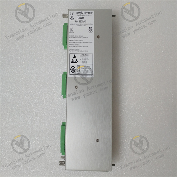
ABB EI803F 3BDH000017R1
Basic Information
Brand: ABB, a global leader in power and automation technologies.
Model: EI803F 3BDH000017R1.
Type: Fieldbus Interface Module.
Origin: Switzerland.
Model: EI803F 3BDH000017R1.
Type: Fieldbus Interface Module.
Origin: Switzerland.
Physical Characteristics
Dimensions: 120mm×80mm×35mm.
Weight: 0.16kg.
Weight: 0.16kg.
Electrical Characteristics
Power Supply Voltage: 24V DC.
Power Consumption: 2.8W.
Power Consumption: 2.8W.
Environmental Requirements
Operating Temperature: -25°C to +60°C.
Storage Temperature: -40°C to +85°C.
Relative Humidity: 5% to 95%, non-condensing.
Storage Temperature: -40°C to +85°C.
Relative Humidity: 5% to 95%, non-condensing.
Communication Functions
Supported Protocols: Profibus DP V0 and V1 communication protocols.
Application Scenarios: Designed for seamless collaboration with ABB's AC 800M and AC 500-S series controllers, suitable for industrial automation systems requiring remote monitoring and data transmission.
Application Scenarios: Designed for seamless collaboration with ABB's AC 800M and AC 500-S series controllers, suitable for industrial automation systems requiring remote monitoring and data transmission.
Working Principle
Used in PLC or DCS (Distributed Control Systems) for field signal acquisition and processing, its working principle is as follows:
I. Basic Positioning and Functions
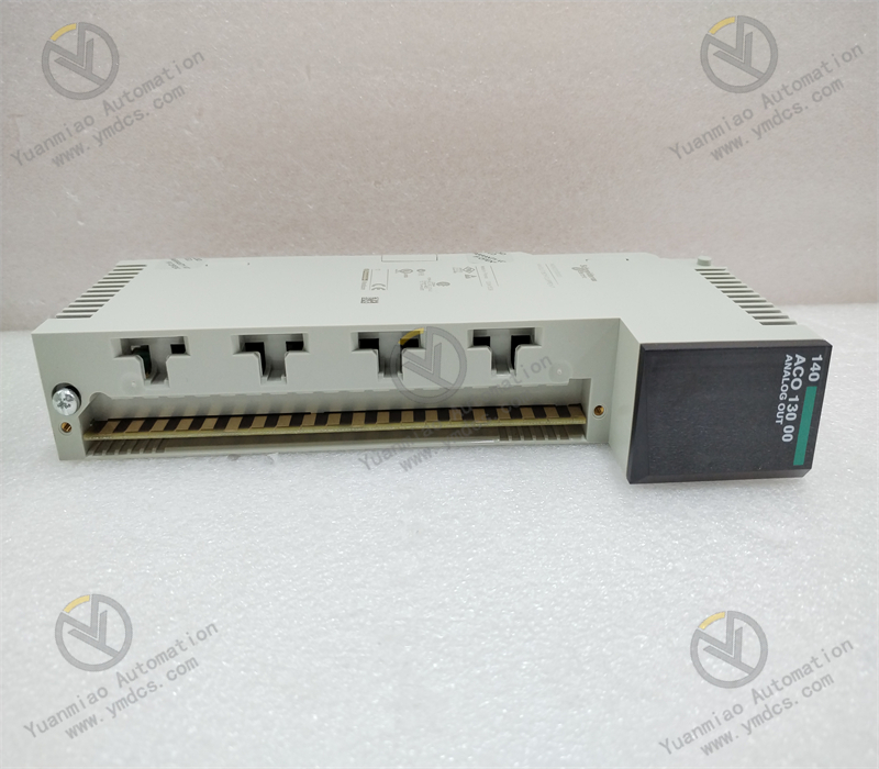
Type: Analog Input Module (AI Module), used to receive and process analog signals from field devices (such as continuously varying signals like voltage, current, temperature, pressure).
Core Function: Converts field analog signals into digital signals recognizable by controllers (such as PLC CPUs) for logical operations, control, or monitoring.
Core Function: Converts field analog signals into digital signals recognizable by controllers (such as PLC CPUs) for logical operations, control, or monitoring.
II. Working Principle
- Signal Input and Preprocessing
- Input Signal Types:
Supports multiple analog signals, including: - Current signals: 4-20mA (industrial standard, strong anti-interference).
- Voltage signals: 0-10V, ±10V, etc.
- Other signals: Temperature signals like RTD (Resistance Temperature Detector) and TC (Thermocouple) (some models require dedicated terminal modules).
- Preprocessing:
- Filters input signals (removes high-frequency noise) and conditions signals (e.g., amplifies or attenuates to ensure signals fall within the module's effective input range).
- Some modules support open-circuit detection (e.g., triggers an alarm when the current signal drops below 3.6mA).
- Analog-to-Digital Conversion (A/D Conversion)
- Core Component: Built-in Analog-to-Digital Converter (ADC) to convert analog signals into digital signals.
- Conversion Principle:
Periodically samples analog signals using the sampling theorem and quantizes samples into binary numbers (e.g., 12-bit, 16-bit, or higher resolution). - Resolution Impact: Higher resolution (e.g., 16-bit corresponding to 65,536 quantization levels) ensures higher conversion accuracy and less signal detail loss.
- Conversion Speed: Depends on module design; high-speed modules support real-time applications (e.g., collecting rapidly changing process parameters).
- Digital Signal Processing and Communication
- Digital Signal Processing:
Converted digital quantities may require linearization (e.g., non-linear compensation for thermocouple temperature-voltage relationships), engineering unit conversion (e.g., converting current values to actual pressure values), and range limiting (setting upper and lower alarm thresholds). - Communication Interface:
Transmits processed digital signals to the controller CPU via the module's internal bus (e.g., FIELDBUS for ABB AC 800M systems). - Communication Protocol: Follows the proprietary protocol of the control system (e.g., ABB's S800 I/O protocol) to ensure data real-time sex and reliability.
- Power Supply and Module Self-Test
- Power Supply Mechanism:
Uniformly powered by the control system's power module; some modules support redundant power input for enhanced reliability. - Self-Test Function:
- Regularly performs hardware self-tests (e.g., ADC accuracy verification, memory status checks).
- When a fault is detected (e.g., power anomalies, channel damage), alarms via LED indicators and sends fault codes to the controller.
III. Typical Application Scenarios
The EI803F module is widely used in industrial scenarios requiring high-precision analog signal acquisition, such as:
- Process Automation: Monitoring temperature, pressure, and flow in chemical, pharmaceutical, and food & beverage industries.
- Power Systems: Collecting electrical parameters like voltage, current, and power in substations.
- Mechanical Equipment Monitoring: Acquiring analog signals (e.g., vibration, rotational speed) for fault diagnosis of large units.
IV. Key Technical Parameters
| Parameter | Typical Value | Description |
|---|---|---|
| Input Channels | 8/16 channels | Supports multi-channel synchronous/asynchronous sampling |
| Resolution | 16-bit | Conversion accuracy |
| Sampling Frequency | 100Hz–1kHz | Varies by channel count and configuration |
| Accuracy Error | ±0.1% F.S. | Full-scale error range |
| Operating Temperature | -40°C ~ +70°C | Industrial-wide temperature design |
| Protection Level | IP20 (cabinet-mounted) | Dust-proof, splash-resistant |
V. Collaboration with Other Modules
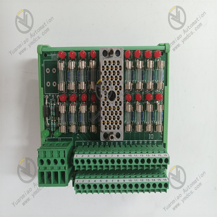
- Connection to Field Devices: Physically connects to sensors and transmitters via terminal modules (e.g., TB801), which provide signal terminals and electrical isolation.
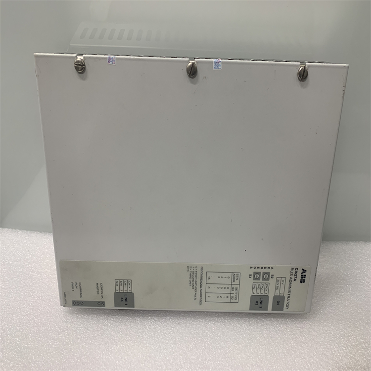
- Interaction with Controllers: Transmits data to PLC/DCS controllers via backplane buses or communication modules (e.g., Communication Processor CM) to enable closed-loop control (e.g., adjusting valve openings based on collected temperature signals).

Common Fault Types and Possible Causes
I. Power-Related Faults
1. No Power Supply / Power Indicator Off
- Causes:
- External power failure (e.g., damaged power adapter, loose or disconnected wiring).
- Internal power circuit failure (e.g., blown fuse, aged capacitor, damaged chip).
- Symptoms: Module cannot start, all indicators are off, no communication or output signals.
2. Unstable or Abnormal Power Voltage
- Causes:
- Input voltage exceeds the module's rated range (e.g., too high/low or fluctuating).
- Failed power filter capacitor, causing excessive ripple.
- Symptoms: Frequent module restarts, flashing indicators, or communication anomalies.
II. Communication-Related Faults
1. No Communication with Controller/System
- Causes:
- Poor communication cable contact, breakage, or wiring errors (e.g., address conflicts, baud rate mismatches).
- Damaged module communication interface (e.g., burned RS-485/Ethernet interface chip).
- Firmware failure or program errors (e.g., incompatible firmware version, program crashes).
- Symptoms: Module shows "offline" or "unrecognized" in the system, or communication timeouts.
2. Communication Data Errors or Packet Loss
- Causes:
- Electromagnetic interference (e.g., nearby motors, inverters).
- Incorrect communication protocol configuration (e.g., parity bit, stop bit errors).
- Faulty internal communication buffer or degraded chip performance.
- Symptoms: Unstable data transmission, frequent parity errors, or data loss.
III. Input/Output (I/O) Faults
1. Input Channel Faults
- No Response to Input Signals
- Faulty external signal source (e.g., damaged sensor, poor switch contact).
- Damaged input channel hardware (e.g., burned current-limiting resistor, failed optocoupler).
- Abnormal input circuit power (e.g., DC power failure, reverse polarity).
- Causes:
- Symptoms: Corresponding channel indicator is off; the system cannot read input signals.
- False Trigger/Misreport of Input Signals
- Signal interference (e.g., unshielded long cables, poor grounding).
- Input channel leakage or component aging (e.g., capacitor leakage causing unstable voltage levels).
- Causes:
- Symptoms: Module shows input active without external signals, or frequent signal state fluctuations.
2. Output Channel Faults
- No Output Signal
- Output load overload or short circuit, triggering module protection (e.g., blown fuse, damaged output transistor/relay).
- Faulty output driver circuit (e.g., damaged driver chip, burned relay coil).
- Causes:
- Symptoms: No voltage/current output on the corresponding channel after system commands, load does not actuate.
- Abnormal Output Signal (e.g., Unstable Voltage/Current)
- Mismatched load characteristics (e.g., inductive load without freewheeling diode, causing back EMF damage).
- Aged output channel components (e.g., oxidized relay contacts, degraded transistor performance).
- Causes:
- Symptoms: Output voltage/current deviates from rated values, or unstable load actuation.
IV. Hardware Physical Faults
1. Module Overheating or Abnormal Heating
- Causes:
- Poor heat dissipation (e.g., inadequate ventilation, severe dust accumulation).
- Internal component short circuit (e.g., burned chip, capacitor breakdown).
- Symptoms: Significant elevated module surface temperature, possibly with unusual odors or smoke.
2. Physical Damage
- Causes:
- Mechanical impact or vibration leading to loose interfaces or cracked circuit boards.
- Environmental factors (e.g., humidity, corrosive gases) causing terminal oxidation or circuit board corrosion.
- Symptoms: Cracked housing, detached terminals, or loose/broken circuit board solder joints.