Description
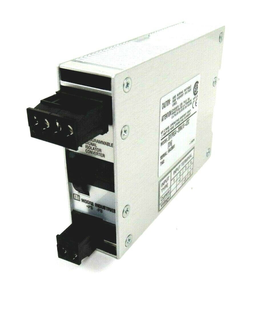
Moore SIY/PRG/4-20MA/10-42DC
I. Product Overview
- Model: SIY/PRG/4-20MA/10-42DC
- Version: Standard Version
- Global Part Number: SIY/PRG/4-20MA/10-42DC
- Product Series: Moore Industries SIY Series
- Product Category: PC Programmable Signal Isolator and Converter
- Country of Origin: United States
Core Functions
This device is a core PC programmable signal isolator and converter from the Moore Industries SIY Series, integrating intelligent digital technology and advanced analog operation with high reliability, precision and ease of use.It is mainly used for isolation, conversion, amplification and transmission of industrial field signals, effectively solving measurement anomalies caused by ground loops and ensuring stable and accurate signal transmission.
The device supports PC programming and can flexibly adapt to various input signal ranges:
- Input: Compatible with current signals from -2.5 mA to 55 mA or voltage signals from -0.5 V to 11 V
- Output: Isolated 4–20 mA standard current signal (4 mA = lower range, 20 mA = upper range)
- Wire break detection: Fault indicated when current falls below 3.6 mA
It uses a 2-wire loop-powered design with no external power supply required.Built-in signal isolation eliminates common path interference; it supports signal splitting to send one input to two receivers and boosts drive capability for additional instruments in the load loop.Equipped with dedicated configuration software and front‑panel terminals, it allows easy programming and high‑accuracy calibration, and includes a NIST test data report.It is a key interface device for industrial process monitoring.
Application Scenarios
Widely used in process automation and monitoring systems in chemical, petrochemical, utilities, oil extraction and refining, pulp and paper, food and beverage, mining and metal refining, pharmaceutical and biotechnology industries.
Suitable for various industrial equipment including tachometer generators, turbine flowmeters, magnetic pickups, dry contact closures, variable frequency drives, rotating machinery, pulse and frequency output sensors, motors and conveyors.It can directly connect to indicators, recorders, PLC, DCS, SCADA and other host systems to solve field problems such as signal interference, incompatibility and overload.
Especially ideal for harsh industrial environments requiring signal isolation, conversion and long‑distance transmission, ensuring accurate and reliable process measurement data and supporting stable operation of industrial automation systems.
II. Technical Specifications
| Parameter Category | Details |
|---|---|
| Electrical Specifications | CPU: High-performance embedded microprocessor for fast programming and signal processingPower Supply: 10–42 VDC wide-range input, 2-wire loop-poweredInput: Programmable; current: -2.5–55 mA (0–20 mA, 4–20 mA, 0–50 mA, 10–50 mA, etc.); voltage: -0.5–11 V (0–5 VDC, 1–5 VDC, 0–10 VDC, etc.); input impedance ≤ 20 Ω (current), ≥ 1 MΩ (voltage)Output: 4–20 mA; programmable range between 4 mA and 20 mA; load capacity ≤ 650 Ω @ 24 VDCIsolation: Full input‑to‑output isolation, eliminates ground loop interferenceCalibration: Factory calibrated with NIST test report; minimum recommended span: 1 mA (current), 250 mV (voltage)Programming: PC programmable via dedicated software and cable, using front-panel terminals |
| Physical Specifications | Mounting: DIN-rail mount, fits standard industrial DIN rails, compact size, compatible with SIY SeriesNet Weight: approx. 0.3 kg (subject to original factory specs)Protection: IP66 (field-mounted version, optional explosion-proof enclosure); board-level protection meets industrial standardsMounting Method: DIN rail or pipe mount (optional 2-inch pipe mounting kit); exposed terminals for easy wiring, programming and maintenance |
| Environmental Adaptability | Operating Temperature: -20°C to +70°C (per factory specs)Storage Temperature: -40°C to +85°CRelative Humidity: 5%–95% (non-condensing)EMI/RFI: High immunity, complies with industrial EMC standards for harsh environmentsCompliance: CSA, IEC, ATEX (optional intrinsic safety), RoHS |
III. Installation & Maintenance Guide
Pre‑installation Requirements
- Anti‑static: Wear a grounded anti‑static wristband during operation. Do not touch board contacts or components with bare hands. Keep the unit in an anti‑static bag until installation.
- Environment: Install in a dust‑free, non‑condensing, well‑ventilated area, away from inverters, high‑voltage cables, high‑power thyristors and other interference/heat sources. For field installation, ensure the enclosure is properly sealed. Maintain -20°C to +70°C.
- Wiring: Follow electrical drawings strictly; separate input, output and power terminals to avoid reverse connection or short circuit. Route communication/programming and power cables in separate ducts using shielded twisted‑pair with single‑end grounding. Tighten all terminal screws. Comply with 2-wire loop wiring rules.
- Configuration: After installation, connect via PC software and programming cable; set input type, range and output ratio as required. Perform power-on test to confirm stable output and correct ratio.
Routine Inspection
- Indicator Lights: Check power, run and fault LEDs. Under normal operation, power and run lights are steady on; fault light is off. If lit, check input, power and wiring for breaks or overload.
- Temperature & Environment: Check for abnormal overheating. Ensure no dust buildup or condensation; verify field enclosure seals. Maintain adequate ventilation.
- Wiring & Terminals: Inspect all terminals and programming ports for looseness, oxidation or burning. Ensure secure grounding and good connections.
- Signal Status: Monitor input and output via host system or meter; confirm correct ratio and stability. Verify proper operation of wire break detection.
Periodic Maintenance
- Every 6 months: Clean dust from the unit and mounting area; retighten terminals; test signal stability and accuracy; clean programming port.
- Annually: Calibrate input/output accuracy with professional instruments; back up configuration; inspect enclosure seals (field version); test immunity and optimize wiring.
- Every 2 years: Perform full hardware test including isolation and channel accuracy; evaluate firmware upgrade (after compatibility check); inspect for aging; consider replacement if performance degrades.
IV. Common Faults & Troubleshooting
| Fault Symptom | Possible Causes | Troubleshooting & Solutions |
|---|---|---|
| No power, no output signal | 1. Abnormal power supply (<10 VDC or >42 VDC)2. Loose, reversed or shorted terminals3. Loop load exceeds 650 Ω4. Internal fuse blown | 1. Verify power is within 10–42 VDC2. Check and correct wiring3. Reduce load to ≤ 650 Ω4. Replace fuse; return for repair if it blows again |
| Abnormal output (unstable, no response, large error) | 1. Bad input or loose wiring2. Incorrect programming (range, type)3. Strong electromagnetic interference4. Calibration expired5. Input/output isolation failure | 1. Check input source and wiring2. Reconfigure parameters via PC software3. Improve shielding and routing4. Recalibrate with standard instruments5. Return for factory repair |
| Programming failed or cannot connect | 1. Damaged or loose programming cable2. Incompatible software version3. Defective programming port4. Unstable power during programming | 1. Replace cable and reconnect2. Install compatible software version3. Clean or repair the port; replace unit if needed4. Ensure stable power supply |
| Unit overheating or abnormally hot | 1. Excessive ambient temperature2. Input voltage too high3. Overload causing high power consumption4. Poor heat dissipation due to dust | 1. Improve cooling and ventilation2. Adjust power to 10–42 VDC3. Reduce loop load4. Clean the unit; return if overheating persists |
| No wire break alarm or false alarm | 1. Wire break detection disabled or misconfigured2. Unstable input signal3. Internal detection circuit fault | 1. Enable and set threshold (recommend <3.6 mA)2. Stabilize input and tighten wiring3. Return for factory inspection |