Description
Praxis 98.6.032.702
I. Overview
In the automatic steel rolling production line of the metallurgical industry, this module can connect detection equipment such as temperature sensors and pressure sensors, collect key data such as roll temperature and rolling pressure in real time, and transmit these data to the control system; at the same time, it receives instructions from the control system to control executive equipment such as cooling water valves and motor start-stop, ensuring that various parameters in the steel rolling process are within the optimal range, thus improving product quality and production efficiency.
II. Technical Parameters
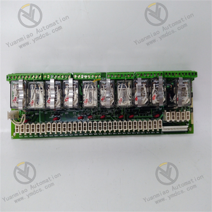
Input channels: Equipped with 16 digital input channels, supporting dry contact and wet contact (NPN/PNP type) signal input. The input voltage range is 10 - 30V DC, and the response time is ≤ 1ms, which can quickly capture the state changes of external equipment, such as signals from the triggering of limit switches and the operation of buttons.
Output channels: Has 12 digital output channels, each with a maximum output current of 1A, and the output voltage is consistent with the power supply voltage (24V DC). It can directly drive loads such as solenoid valves and small contactors, meeting the driving needs of most industrial control scenarios.
Isolation performance: Optoelectronic isolation is adopted between input, output and power supply, with an isolation voltage ≥ 2500V AC (for 1 minute), which effectively suppresses electromagnetic interference in industrial sites and ensures the accuracy of signal transmission and the safe operation of the module.
Environmental adaptability: The operating temperature range is -25°C to +70°C, allowing stable operation in cold or high-temperature industrial environments; the relative humidity is 5% - 95% (no condensation), adapting to humid environments; the vibration resistance is 10 - 500Hz with an acceleration of 10g, and the impact resistance is 50g (11ms half-sine wave), which can cope with the vibration and impact effects in industrial sites.
Communication interface: Integrates 1 RS-485 communication interface, supporting MODBUS RTU communication protocol. The data transmission rate can be selected from various rates such as 9600bps and 19200bps, facilitating data interaction with equipment such as PLCs and upper computers to achieve remote monitoring and control.
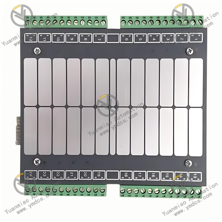
Dimensions: Adopts standard DIN rail mounting design, with dimensions of 120mm × 80mm × 60mm (length × width × height). It is compact in size, saving installation space in the control cabinet.
III. Functional Features
Fast signal response: The input channel response time is ≤ 1ms, which can quickly capture the state changes of external equipment, ensuring that the control system can obtain on-site information in a timely manner and respond; the output channel can quickly execute control commands, improving the control accuracy and real-time performance of the system, especially suitable for automated production lines with high requirements for response speed.
Strong anti-interference capability: Through optoelectronic isolation technology and reasonable circuit design, the module has excellent anti-electromagnetic interference capability, and can work stably in industrial environments with strong interference sources such as motors and frequency converters, avoiding problems such as signal distortion and misoperation caused by interference, and ensuring the reliable operation of the system.
Flexible communication and integration: Supports MODBUS RTU communication protocol, which can seamlessly connect with various industrial control equipment, facilitating integration into existing automation systems. The standard DIN rail mounting method makes the module easy to install and can be quickly integrated into the control cabinet, shortening the system construction cycle.
Status indication and diagnosis: The surface of the module is equipped with status indicators for input and output channels and a power indicator, which can intuitively display the working status of each channel and the power supply situation. At the same time, it has a communication fault diagnosis function. When communication is abnormal, it can indicate the fault through a specific indicator light flashing mode, facilitating operators to quickly troubleshoot problems.
IV. Common Faults and Solutions
Possible causes: Loose or poor contact of input channel wiring; input signal voltage exceeding the allowable range of the module; input channel burned out; failure of optoelectronic isolation components.
Solutions: Check the input channel wiring, re-plug and fasten the connection terminals; use a multimeter to measure the input signal voltage to ensure it is within the 10 - 30V DC range; if the channel is suspected to be burned out, switch the signal to other spare channels for testing, and replace the module if it is confirmed to be burned out; if the optoelectronic isolation component is faulty, replace the corresponding internal component of the module or replace the entire module.
Output channel cannot drive the load
Possible causes: Incorrect wiring of the output channel; load current exceeding the maximum output current of the channel (1A) leading to channel protection; damage to the output triode or relay; insufficient power supply voltage of the module.
Solutions: Check the output channel wiring to ensure correct connection of positive and negative poles; replace the load with appropriate power or add an intermediate relay to expand the load capacity; use a multimeter to detect the conduction status of the output channel, and replace the damaged component or module if the component is confirmed to be damaged; measure the module's power supply voltage to ensure it is 24V DC and stable, and check the power supply and lines if the voltage is insufficient.
Communication interruption
Possible causes: Open circuit or short circuit of the RS-485 communication line; inconsistent settings of communication protocol parameters (baud rate, address, etc.); damage to the communication interface; excessive bus load.
Solutions: Use a multimeter or oscilloscope to detect the communication line and repair open or short circuit points; check and unify the communication protocol parameters of the module and the upper computer; replace the communication interface or module; reduce the number of devices on the bus, or add an RS-485 repeater to enhance the signal.
Frequent restart or no power supply of the module
Possible causes: Faulty or unstable voltage of the power supply; loose power supply wiring; damage to the internal power supply circuit of the module; strong electromagnetic interference in the external environment affecting power supply stability.
Solutions: Replace with a stable power supply to ensure the output voltage is 24V DC; check the power supply wiring and fasten the connection terminals; if the internal power supply circuit is damaged, repair or replace the module; take anti-interference measures such as grounding and shielding to reduce the impact of electromagnetic interference on the power supply.