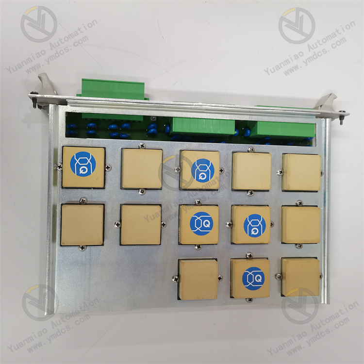
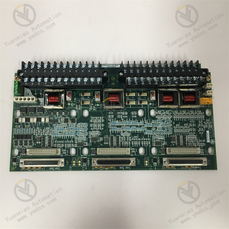
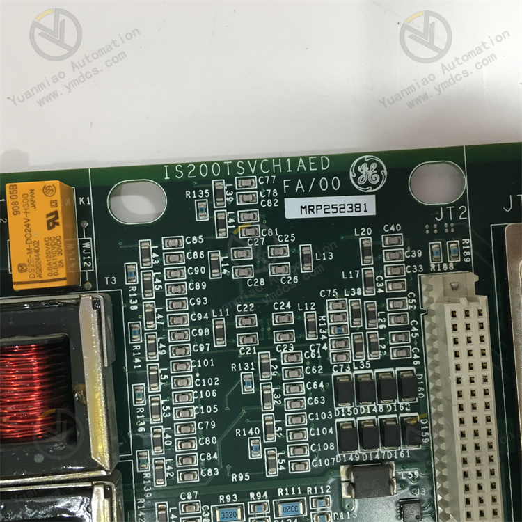
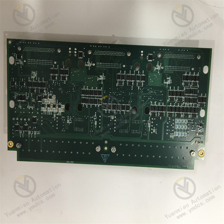
Description
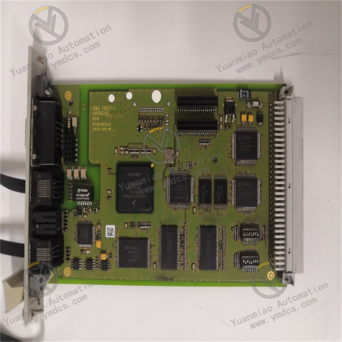
GE IS200TSVCH1AED
I. Functional Features
High-Performance Control Capability
- Likely used in critical control loops of industrial automation systems, supporting complex logic operations and real-time control. Suitable for applications in power, chemical, manufacturing, and other industries.
- Equipped with fast data processing capabilities to respond to high-frequency input signals (e.g., sensor pulses, analog quantity changes), ensuring control accuracy.
Multiple Input/Output Interfaces
- May integrate analog input/output (AI/AO) and digital input/output (DI/DO) interfaces, supporting connections to sensors (e.g., temperature, pressure, flow) and actuators (e.g., valves, motors).
- Supports Hall effect pulse inputs for acquiring rotational speed or position signals of rotating equipment.
High-Reliability Design
- Utilizes industrial-grade hardware (e.g., wide-temperature operation, vibration/shock resistance) to adapt to harsh environments (-40°C to 70°C).
- May support redundancy configurations (e.g., power redundancy, communication redundancy) to reduce single-point failure risks and ensure continuous system operation.
Flexible Communication Capability
- Supports multiple industrial communication protocols (e.g., Modbus, EtherNet/IP, PROFINET, etc.), enabling seamless integration with PLCs, DCS systems, or host computers.
- Features real-time data transmission capabilities, synchronizing data to control systems or monitoring platforms via embedded agent technologies (e.g., EFA).
Modular Design
- Compatible with other GE series modules (e.g., IS200, IS420 series), facilitating system expansion and maintenance.
II. Technical Parameters
| Parameter | Description |
|---|---|
| Processor | May be equipped with an Intel or specialized industrial-grade processor, with a main frequency ≥ 100MHz, supporting multi-threaded processing. |
| Storage | Built-in Flash/EEPROM for program storage, RAM for real-time data processing, supporting firmware upgrades. |
| I/O | - Analog Input: 2×12-bit/16-bit (e.g., 4-20mA, 0-10V) - Digital I/O: 4×DI/4×DO (24V DC) - Pulse Input: 2×Hall effect (50kHz frequency) |
| Communication Interfaces | - Ethernet (10/100Mbps) - RS-485/RS-232 - May support Profibus or CAN bus |
| Power Supply | 24V DC or 100-240V AC (wide voltage input, adapting to industrial power fluctuations) |
| Operating Temperature | -40°C to 70°C (industrial-grade wide temperature range) |
| Dimensions | Approximately 100mm×200mm×50mm (compact design suitable for cabinet installation) |
| Certifications | CE, UL, ATEX (explosion-proof certification, may be applicable to hazardous areas) |
III. Working Principle
Signal Acquisition
- Acquires continuous signals (e.g., temperature, pressure) through analog input interfaces, switch signals (e.g., equipment start/stop status) through digital input interfaces, and frequency signals of rotating equipment through pulse input interfaces.
- Signals are conditioned (filtered, amplified) and converted to digital quantities by an analog-to-digital converter (ADC) for transmission to the processor.
Data Processing and Control
- The processor processes data according to preset control algorithms (e.g., PID control, logic operations) to generate control commands.
- Drives actuators through analog output interfaces (DAC) or digital output interfaces to adjust valve openings, motor speeds, etc.
Communication Interaction
- Exchanges data with host computers (e.g., SCADA systems) or other controllers via communication interfaces, uploading real-time status and receiving remote commands.
- Supports master-slave mode or peer-to-peer communication to ensure reliable data transmission across multiple devices.
IV. Common Faults and Solutions
| Fault Type | Phenomenon | Possible Causes | Solutions |
|---|---|---|---|
| Power Supply Fault | Module has no power indicator and cannot start | - Faulty power adapter - Abnormal input voltage - Internal fuse blown | - Check power connections and measure input voltage - Replace power adapter or fuse - Contact maintenance personnel to inspect internal circuits |
| Communication Fault | Unable to communicate with the host computer, data interruption | - Damaged communication cable - Incorrect parameter settings (baud rate, address) - Faulty interface chip | - Replace cable and check wiring - Reconfigure communication parameters - Replace module or repair interface circuit |
| Abnormal Input Signal | Analog input values fluctuate or read zero | - Faulty sensor - Poor cable shielding (electromagnetic interference) - Loose interface connections | - Calibrate or replace the sensor - Check cable shielding and grounding - Re-plug terminals to ensure secure connections |
| No Output Response | Actuator does not operate, output indicator off | - Damaged output channel - Actuator power failure - Control logic error | - Test output channels with a multimeter - Check actuator power supply - Debug control programs to confirm command correctness |
| Overheating Alarm | Module overheats and automatically shuts down | - Poor heat dissipation - Ambient temperature exceeding rated range | - Clean dust from module cooling vents - Improve ventilation or install a fan - Check if installation clearance meets requirements (≥4 inches) |

V. Operation Guide
Installation Requirements
- Mechanical Installation: Vertically mount on a standard rail or cabinet panel, ensuring at least 4 inches (≈10cm) of cooling space above and below the module to avoid dense stacking.
- Environmental Requirements: Install in a dry, non-corrosive, low-electromagnetic-interference location, away from high-power cables.
Wiring Steps
- Power Wiring: Confirm input voltage type (DC/AC), use flame-retardant cables to connect power terminals, and ensure reliable grounding (protective earth PE).
- Signal Wiring:
- Analog Signals: Use shielded twisted-pair cables, avoid parallel routing with power cables to reduce interference.
- Digital Signals: Differentiate between input/output terminals and pay attention to voltage levels (e.g., 24V DC).
- Communication Wiring: Connect corresponding pins as per protocol requirements (e.g., A/B lines for Modbus RTU), and install terminating resistors as needed.
Parameter Configuration
- Configure via GE proprietary software (e.g., Proficy Machine Edition) or third-party tools:
- Communication Parameters: Set baud rate, data bits, stop bits, slave address, etc.
- I/O Mapping: Define the physical signal types for each channel (e.g., AI1 corresponding to a temperature sensor).
- Control Parameters: Configure PID coefficients, alarm thresholds, safety interlock logic, etc.
Debugging and Maintenance
- Pre-power-up Checks: Ensure correct wiring, compatible power voltage, and tight terminal screws.
- Function Testing:
- Analog Input: Apply standard signals to sensors and check if software readings are correct.
- Digital Output: Force outputs via software and observe actuator movements and indicator status.
- Routine Maintenance:
- Regularly clean module dust and check for loose cable connections.
- Record operation logs and analyze abnormal data (e.g., communication delays, output fluctuations).
- Periodically power on spare modules for testing to prevent capacitor aging from long-term idling.