Description
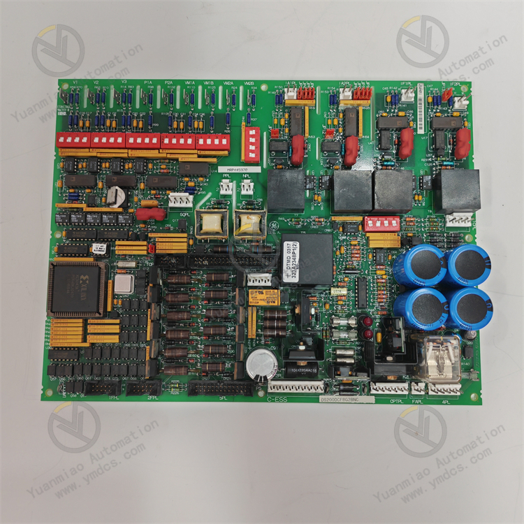
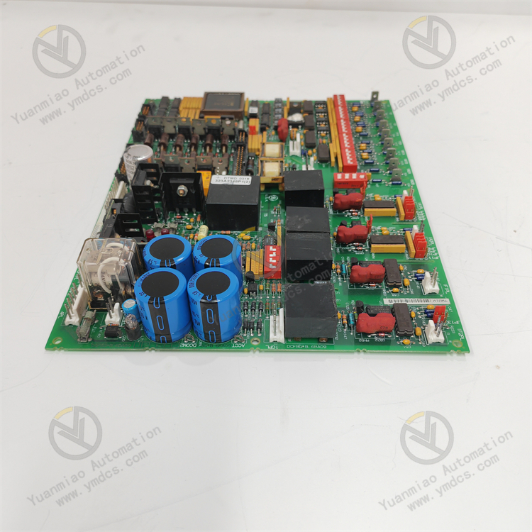
GE DS200DCFBG2BNC
GE DS200DCFBG2BNC is a simplex servo I/O terminal board manufactured and designed by General Electric, and it is part of the Mark VI series used in GE Speedtronic control systems.
Functional Features
- Multiple Signal Processing: Equipped with two servo outputs, I/O for six LVDT position sensors, and two active pulse rate inputs for flow monitoring, it can handle various types of signals to meet different measurement and control requirements.
- Configurable Current: The servo coil current can be selected between 10 to 120mA via jumpers, adapting to servo valves of different specifications and enhancing the board's versatility and flexibility.
- System Diagnosis Support: Connectors JR1 and J5 are connected to the on-board ID chip signals, facilitating system identification and diagnosis of the board, which helps quickly locate and resolve system faults.
- Compact Installation Design: To save cabinet space, the terminal board can be vertically stacked on a DIN rail. Additionally, two DSVO boards can be linked to VSVO if necessary, enabling easy expansion.
Technical Parameters
- Input Voltage: Typically 24V DC.
- Output Voltage: 0–10V DC.
- Communication Interface: RS485.
- Operating Temperature: -40°C–85°C.
- Dimensions: Approximately 100mm×80mm×50mm.
- Weight: 200g.
Installation and Wiring
- Install the DSVO board into a plastic bracket and then mount it on a DIN rail.
- The terminal block accepts direct-connected servo I/O cables. Use twisted-pair wires with #18 AWG shielding. For SCOM (ground) connections, six screws numbered 31 to 36 are provided and should be used with the shortest possible distance.
Configuration Method
- The coil resistance of servo valves ranging from 22W to 1000W and the required coil current are selected via jumpers JP1 and JP2 on DSVOH1B.
General Operation Guide for GE DS200DCFBG2BNC
Installation
- Select an appropriate installation location to ensure the environment meets the module's operating requirements, such as suitable temperature, humidity, and no strong electromagnetic interference.
- Fix the module on the mounting base or inside the control cabinet using appropriate installation tools according to the module's specifications, ensuring a secure installation to prevent looseness due to vibration or other factors.
- Connect relevant cables, including power cables, communication cables, and signal cables to other devices, ensuring correct and secure connections to avoid poor contact or short circuits.
Configuration
- Determine control tasks and functional requirements, and clarify the digital input/output channels to be used and related parameter settings, such as delay time and timing accuracy.
- Configure parameters for the module through dedicated programming software or a host computer control system. Set communication parameters (e.g., communication protocol, baud rate, IP address) to enable normal communication with other devices.
- Configure the functions of digital input/output channels according to specific applications. For example, assign digital input channels to corresponding signal sources (e.g., load protection, pressure switches, vibration switches) and set their delay time parameters; associate digital output channels with devices or actuators to be controlled.
Debugging
- Before formal operation, check if the module's power supply is normal, ensuring the input voltage is within the specified range and the power indicator light is on.
- Verify that all hardware connections are secure, including cables and connections between the module and other devices.
- Test the functionality of digital input/output channels by sending test signals or simulating actual working conditions. For example, input different signals to digital input channels to check if the module can correctly identify and process them; output signals through the module to check if connected devices or actuators operate as expected.
- Check the communication status using relevant diagnostic tools or commands to test the communication link between the module and other devices, ensuring correct data transmission and reception.
- Verify that configured parameters and control logic meet design requirements, and troubleshoot and correct issues promptly if they arise.
Operation and Monitoring
- Put the module into operation and monitor its working status in real time. Observe whether the module is operating normally and if there are any fault alarms through the host computer monitoring system or the module's own status indicator lights.
- Regularly inspect the module's working status, including temperature and fan operation, to ensure it operates in good condition. Take timely measures to address issues such as excessively high module temperature or fan failure.
- Monitor changes in digital input/output signals and data interaction with other devices to ensure control functions in industrial production are properly implemented.
Maintenance and Care
- Regularly clean dust and debris from the module's surface to maintain good heat dissipation and prevent excessive dust accumulation from affecting the module's heat dissipation performance and normal operation.
- Periodically inspect the connections of power cables, communication cables, and signal cables as recommended in the equipment maintenance manual, and tighten them promptly if loose.
- Regularly upgrade the module's software as recommended by the manufacturer based on actual usage to improve performance, functionality, and stability, and fix potential software vulnerabilities.
- Periodically inspect and maintain hardware, such as checking for damage or aging of the module's electronic components, and replace relevant components promptly if necessary.

Troubleshooting
- Preliminary Checks: Verify the power supply is normal, including whether the input voltage is within the specified range and whether the power indicator light is on. Ensure all hardware connections (including cables to other devices) are secure. Check the LED status indicators on the module's front panel and refer to the user manual to determine the fault type. Additionally, check if the working environment's temperature and humidity meet requirements.
- System-Level Troubleshooting: For communication faults, check if communication interface parameters (e.g., communication protocol, baud rate, IP address) are correctly set and match other devices. Use relevant diagnostic tools or commands to test the communication link. For digital input/output module faults, check the module's status via the controller's diagnostic functions or host computer software, and verify whether input values change correctly and outputs respond. Try replacing suspected modules to observe if the fault shifts. If software or configuration issues are suspected, check the program logic for errors, compare the current configuration with backup files to confirm if parameters have been accidentally modified, and try restarting the module to rule out temporary software glitches.
- Utilizing Diagnostic Tools and Resources: Refer to the LED status code descriptions in the user manual to diagnose faults. Use GE's dedicated diagnostic software to read system event logs and fault codes, and monitor key variables online through the software to locate anomalies. When necessary, use hardware testing tools to test suspected components (e.g., replace related modules one by one using the substitution method) and perform loopback tests on communication ports to verify physical layer integrity.
- Fault Handling and Documentation: For emergency faults (e.g., module smoking or unusual odors), power off immediately and isolate the device to prevent fault escalation. For critical faults affecting production, switch to standby equipment or modules if the system supports redundancy. Record the fault occurrence time, symptoms, related variable values, and operation history, and save system logs and error codes to provide detailed information when contacting GE technical support.