Description
B&R 7DI140.70
I. Overview
This module can receive switching signals from various sensors (such as proximity switches, photoelectric sensors, travel switches, etc.). These signals usually indicate the operating status of equipment (such as "running" or "stopped"), position status (such as "in place" or "not in place"), etc. Relying on B&R's technical strength in the field of automation, the 7DI140.70 module features high reliability, fast response speed and good anti-interference ability. It can adapt to the complex environments of various industrial scenarios such as machinery manufacturing, automobile assembly, and logistics transportation, providing a guarantee for the stable operation of automation systems.
II. Technical Parameters
Input signal type: Supports DC input signals, usually adapting to 24V DC standard industrial signals. This is a widely used signal type in the industrial field with strong compatibility and can be used with various sensors.
Input current: The input current of each channel is usually within a certain range (such as 3mA - 10mA, specific parameters are subject to the product manual). It can reliably detect the switching signals sent by sensors, ensuring the accuracy of signal collection.
Response time: The response time of input signals is short, generally at the millisecond level (such as below 1ms, specific values refer to the product manual). It can quickly capture changes in signals, timely reflect the status of on-site equipment, and meet the real-time requirements of high-speed automation systems.
Electrical isolation: An electrical isolation design is adopted between the input channels and the backplane bus. The isolation voltage can usually reach more than 2500V AC, which effectively suppresses common-mode interference and series-mode interference in industrial sites, prevents external electrical interference from affecting the module and control system, and ensures the stable operation of the system.
Power supply requirements: Usually powered by the I/O rack where it is located or a dedicated power module. The typical supply voltage is 24V DC, with low power consumption, which has little impact on the load of the system power supply and is convenient for system integration.
Environmental adaptability:
- Operating temperature: Can work stably within the temperature range of 0°C - 60°C, and can cope with common temperature changes in industrial sites.
- Relative humidity: Can operate normally in a relative humidity environment of 5% - 95% (non-condensing), suitable for humid production workshops and other environments.
- Vibration and shock resistance: Complies with relevant industrial standards, has certain vibration and shock resistance capabilities, and can work reliably in occasions with slight vibrations (such as near production lines and machine tools).
III. Functional Characteristics
Reliable electrical isolation: The electrical isolation design can not only effectively block the propagation of external interference signals, protect the module and control system from external electrical faults, but also improve the anti-interference ability of the system and ensure the accuracy of signal collection.
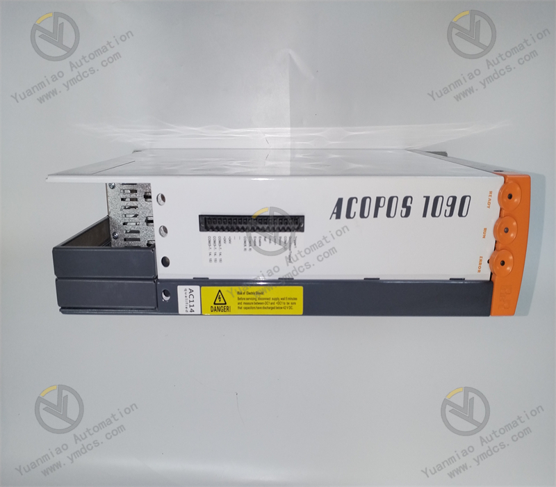
Status indication function: The module is equipped with LED status indicators for each input channel. When the channel receives an "ON" signal, the indicator light is on; when it receives an "OFF" signal, the indicator light is off. Operators can intuitively understand the signal status of each channel through the indicator lights, which is convenient for system debugging, operation monitoring and fault troubleshooting.
Flexible configuration method: The module can be configured through B&R's Automation Studio programming software, such as setting parameters like the filtering time of input signals, to adapt to the signal characteristics of different sensors and improve the adaptability and versatility of the module.
Convenient installation and integration: Adopts a standardized rail mounting method, making the installation process simple and fast. It can be flexibly combined with other B&R I/O modules, PLCs and other equipment to form a compact automation control system. At the same time, the module has good compatibility with the entire automation system, enabling seamless integration and improving the efficiency of system construction.
IV. Common Faults and Solutions
Phenomenon: The on-site sensor has sent a signal (such as the sensor indicator light is on), but the corresponding input channel of the module has no signal display, the LED indicator light is off, and the control system cannot receive the signal.
Causes and solutions:
- Wiring failure: Check whether the wiring between the sensor and the module is correct and firm, and whether there is disconnection, poor contact, etc. Reconnect the lines to ensure that the wiring is firm and reliable, and replace the damaged wires if necessary.
- Sensor failure: Check whether the sensor is working normally, such as whether the sensor power supply is normal and whether the sensor is damaged. Use a multimeter to detect the output signal of the sensor. If the sensor is faulty, just replace the sensor.
- Incorrect channel configuration: Check whether the channel configuration of the module in the programming software is correct, such as whether parameters like input type and address allocation are consistent with actual needs. After reconfiguring the parameters correctly, re-download the program and test.
False signal reporting or instability
Phenomenon: The LED indicator of the module's input channel flickers frequently, or the indicator light is on when there is no signal input, causing the control system to receive wrong signals.
Causes and solutions:
Phenomenon: The LED indicator of the module's input channel flickers frequently, or the indicator light is on when there is no signal input, causing the control system to receive wrong signals.
Causes and solutions:
- Interference impact: Strong electromagnetic interference (such as motors, frequency converters and other equipment) in industrial sites may cause signal distortion. The following measures can be taken: replace the signal line with a shielded wire and reliably ground the shield layer at one end; arrange the signal line away from the interference source; appropriately increase the filtering time of the input signal through programming software.
- Power fluctuation: The power supply voltage of the module or sensor is unstable, leading to abnormal signal collection. Check whether the power supply voltage is within the specified range. If the voltage fluctuates greatly, a voltage stabilizing device can be added or a stable power supply can be replaced.
- Sensor installation problem: The sensor is installed in an improper position or loose, resulting in unstable detection signals. Readjust the installation position of the sensor to ensure that it is firm and reliable and can stably detect the target signal.
Module communication failure
Phenomenon: The module cannot communicate with the control system, and the control system cannot obtain the signals collected by the module nor configure the module.
Causes and solutions:
Phenomenon: The module cannot communicate with the control system, and the control system cannot obtain the signals collected by the module nor configure the module.
Causes and solutions:
- Communication line failure: Check whether the communication line between the module and the control system is connected correctly and firmly, and whether there is disconnection, short circuit, etc. Re-plug the communication connector to ensure reliable connection; use special instruments to detect the signal transmission of the communication line and eliminate line faults.
- Mismatched communication parameters: Check whether the communication parameters of the module (such as baud rate, address, protocol, etc.) are consistent with the settings of the control system. Reset the communication parameters of the module in the programming software to match the control system.
- Module hardware failure: If the communication line and parameters are normal, the communication interface or internal circuit of the module may be damaged. Contact professional maintenance personnel for inspection and replace the module if necessary.


