Description
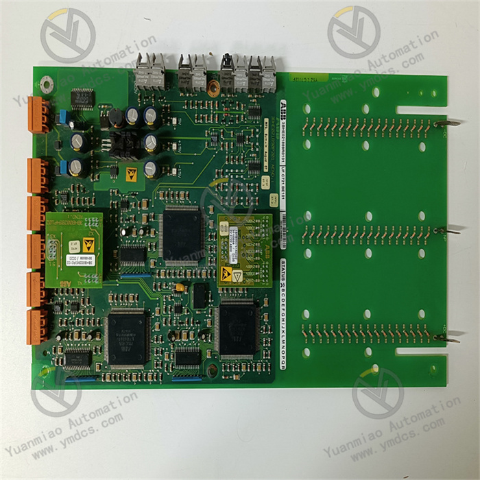
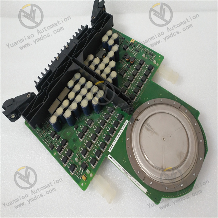
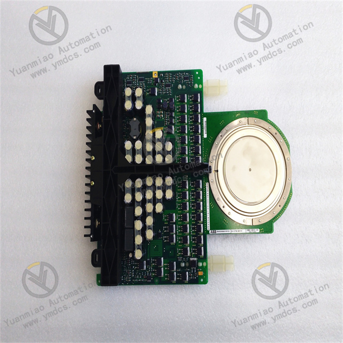
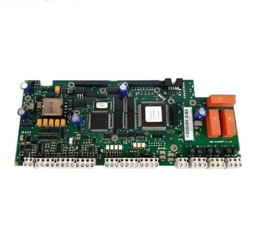
ABB RMIO-01C
I. Basic Information
Model: RMIO-01CMaterial Code: 64538012Brand: ABBCompatible Equipment: ABB ACS800 series single-drive and multi-drive inverters, serving as the core main control I/O board of the inverter.Product Type: Motor control I/O main board, integrating inverter logic control, digital/analog signal acquisition, encoder feedback, upper computer communication and fault detection functions. It is the core hardware unit for the inverter to realize start-stop speed regulation, status collection and interlock protection, supporting local field control, remote PLC linkage and closed-loop speed regulation of motors.
Product Positioning
As the standard main control board of ACS800 inverters, RMIO-01C is equipped with a 32-bit DSP processor and built-in DTC direct torque control algorithm, which can realize high-precision speed regulation of asynchronous motors and permanent magnet synchronous motors. The board integrates multiple configurable I/O terminals, pulse encoder interfaces and RS-485 communication interfaces. It can collect switch and analog signals from field buttons, pressure and temperature sensors, feed back equipment operating status and fault signals to the upper system, and supports networking with PLC and DCS via Profibus and Modbus RTU field buses. Widely used in thermal power, metallurgy, petrochemical, water treatment and other high-power fan, water pump and compressor variable frequency speed regulation scenarios to ensure stable, accurate and safe operation of transmission systems.
Hardware Architecture
- Main Control Operation Unit: Adopts DSP digital signal processor with built-in DTC control program, realizing three closed-loop regulation of current, speed and torque, dynamic response ≤5ms, speed control accuracy ±0.01%, torque control accuracy ±3%.
- I/O Signal Acquisition Unit: Integrates multi-channel digital input, relay output, analog input and output terminals, compatible with sink/source wiring, freely configurable for start-stop, emergency stop, multi-speed, fault alarm and status feedback functions.
- Encoder Feedback Unit: Reserved incremental pulse encoder interface to collect high-speed pulse signals for closed-loop vector speed control under high-precision positioning and heavy-load low-speed working conditions.
- Bus Communication Unit: Onboard RS-485 hardware circuit, expandable for Profibus DP and Modbus RTU protocols, realizing remote parameter reading and writing, operating status monitoring and fault uploading of inverters.
- Power & Fault Detection Unit: Powered by external 24VDC, built-in overvoltage, undervoltage, short-circuit and surge protection circuits. It monitors the operating status of power supply, drive circuit and I/O circuit in real time, locks fault codes and blocks inverter output pulses when abnormalities occur.
Mounting Specification
- Power Supply: 24VDC (±10%), typical power consumption 250mA
- Mounting Mode: Card slot hot-plug installation inside the inverter, connected via standard backplane connector
- Overall Dimension: 105mm×75mm×35mm
- Net Weight: 0.5kg
- Protection Class: IP20 (must be installed inside the inverter control cabinet)
- Supporting Debug Tools: ABB DriveWindow software, 24VDC regulated power supply, multimeter, shielded communication cable
Supporting System
Supporting Hardware
ACS800 inverter power unit, AGDR series IGBT drive board, incremental encoder, fieldbus communication adapter, 24VDC DC power supply, shielded control cable.
Debug Tools: DriveWindow, insulation resistance tester, oscilloscope, anti-static wristband.
Upper System: PLC, DCS, SCADA monitoring platform for remote parameter configuration and equipment centralized monitoring.
Typical Industries: Thermal power, metallurgy, petrochemical, municipal water treatment, mining and building materials industries.
Product Features
- High-performance DTC direct torque control, supporting sensorless and sensor-based closed-loop speed regulation for smooth heavy-load startup of various AC motors.
- Freely configurable multi-channel I/O terminals, supporting PID closed-loop regulation, external safety interlock and multi-section speed control to adapt to local and remote dual control schemes.
- Native RS-485 bus hardware design, compatible with mainstream industrial field buses, reducing field control cable wiring cost for multi-inverter centralized control.
- Built-in surge, short-circuit and reverse connection protection for I/O and power supply circuits, with fault code latch function for rapid maintenance troubleshooting.
- Wide temperature range operation, compliant with industrial EMC electromagnetic compatibility standards, stable operation in dusty and high-low temperature control cabinets.
- Hardware interchangeable within the same ACS800 series, only parameter downloading is required after board replacement to resume equipment operation and shorten maintenance downtime.
II. Technical Specifications
2.1 Electrical Parameters
- Rated Supply Voltage: DC24V (21.6V~26.4V)
- Digital Input (DI): 8 channels, sink/source configurable, 24VDC input level
- Relay Digital Output (DO): 8 channels, contact rating 2A/250VAC, passive relay contact
- Analog Input (AI): 2 channels, 0~10V / 4~20mA configurable
- Analog Output (AO): 2 channels, 0~10V / 4~20mA for speed and current signal transmission
- Encoder Interface: Incremental quadrature pulse input, max. 1200Hz input frequency
- Communication: Isolated RS-485, baud rate 9.6kbps~12Mbps adjustable
- Control Modes: DTC, V/F, vector control
- Withstand Voltage: 2500VAC between I/O circuit and main control circuit
2.2 Mechanical Parameters
- Mounting: Internal card slot plug-in installation of inverter
- Dimension: 105mm(L)×75mm(W)×35mm(T)
- Net Weight: 0.5kg
2.3 Environmental Parameters
- Operating Temperature: -25℃ ~ +60℃
- Storage Temperature: -40℃ ~ +85℃
- Humidity: 5%~95%RH, non-condensing, no corrosive and conductive dust
III. Key Features
- Core logic speed regulation of inverter: Generate PWM drive signals based on given frequency and start-stop commands to adjust motor voltage and frequency for energy-saving speed control of fans, pumps and heavy-duty equipment.
- Field I/O signal acquisition and safety interlock: Collect emergency stop, remote switching and process analog signals to realize equipment interlock protection and automatic PID adjustment according to preset logic.
- Equipment status and fault feedback: Output passive contact signals of ready, running, fault and overload to field indicator lights and PLC for real-time equipment condition monitoring.
- Encoder closed-loop speed control: Collect motor actual speed pulse signals to eliminate speed deviation and improve low-speed heavy-load control stability.
- Remote centralized monitoring via fieldbus: Realize remote command issuing, operating data collection and fault alarm uploading to realize factory-level intelligent equipment management.
- Automatic fault protection and diagnosis: Block PWM pulses and lock fault codes once overcurrent, overvoltage, short-circuit and external interlock faults are detected to avoid damage to motors and power units.
IV. Working Principle
The 24VDC external power supply supplies power to the main control, I/O and communication circuits of RMIO-01C. After power-on initialization, the DSP main controller loads inverter parameters to complete function configuration.Under local control, field start-stop, emergency stop and multi-speed switch signals are collected via DI terminals, while process pressure and flow signals are collected via AI terminals. Under remote control, start-stop and frequency commands are issued by PLC through RS-485 bus. The main controller calculates PWM drive pulses via DTC algorithm and transmits them to the IGBT drive board to adjust the motor output voltage and frequency.The motor encoder feeds back actual speed pulses to form a closed-loop speed control system to guarantee high-precision speed regulation. Meanwhile, the board monitors bus voltage, output current and I/O loop status in real time. Once faults are detected, the drive pulses will be immediately blocked, fault codes latched and alarm signals uploaded to trigger safety interlock shutdown.
V. Application Scenarios
- Energy-saving retrofit of auxiliary equipment in thermal and hydropower plants: Induced draft fans, forced draft fans and circulating water pump ACS800 inverter control systems.
- Heavy-duty transmission equipment in metallurgy and mining: Blast furnace fans, belt conveyors and rolling mill main drive frequency conversion local interlock and DCS remote monitoring systems.
- Process compressors and circulating pumps in petrochemical plants: Safety interlock and automatic speed regulation via I/O terminals and fieldbus communication.
- Aeration fans and booster pumps in municipal water treatment plants: Dual local/remote automatic control of frequency conversion equipment.
- Maintenance replacement of aging main control boards for old ACS800 inverters, reusing existing wiring and parameter programs to reduce renovation downtime and debugging costs.