Description
1. Overview
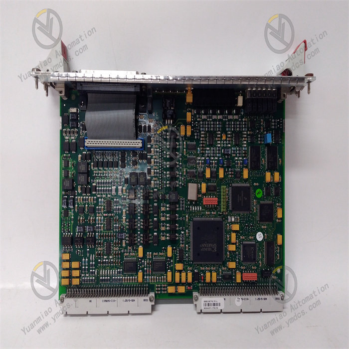
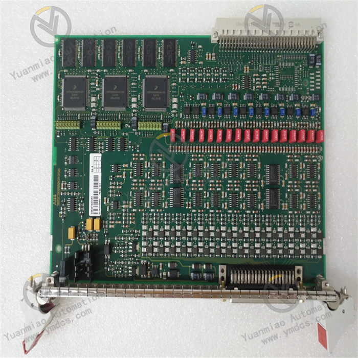
ALSTOM SDK-C0147 is a high-performance backplane bus signal interface module specially designed for power plant turbine control systems, generator excitation systems, combined cycle DCS and power relay protection systems. Its complete identifiers include main model SDK-C0147, hardware batch code 12004-101-00 and embedded firmware version SBS04M17C. It belongs to the core hardware product line of ALSTOM/GE Vernova power control, and serves as the fundamental core unit for data communication and signal link transmission among turbine main control modules, servo drive modules, IO acquisition modules and excitation control modules.
The module undertakes core functions including system backplane bus networking, multi-board data relaying, isolated signal transmission, bus timing scheduling, loop impedance matching and hardware link self-testing. It provides a stable, standardized and anti-interference underlying bus transmission channel for the entire control system, acting as the core supporting hardware to guarantee accurate transmission of unit regulation logic, servo closed-loop control and interlock protection signals.
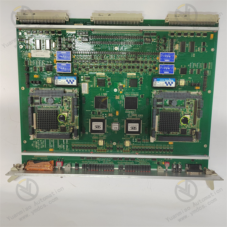
Adopting an industrial bus architecture and integrated backplane circuit design, the PCB integrates multiple functions such as bus signal conditioning, impedance matching, electrical isolation, data relaying and link monitoring. Different from conventional functional boards, it specializes in constructing underlying bus networks and standardizing signals of control systems, solving common industry pain points including interference from concurrent communication of multiple modules, signal attenuation, timing disorder and unstable links. Specially optimized for harsh power plant operating conditions such as severe electromagnetic radiation, power grid fluctuation, alternating temperature & humidity variation, 24/7 non-stop continuous operation and high-frequency data interaction among multiple boards, the unit contains no wearable mechanical structures with zero long-term bus drift, data packet loss or link disconnection. Natively fully compatible with cabinet backplane buses, slot architectures and system configurations of all ALSTOM and GE turbine control systems, excitation control systems and power protection systems, it features outstanding universality and interchangeability. It is a standardized core backplane module for bus networking matching of new unit control systems, optimization of bus links for legacy control systems, replacement of faulty backplane modules and life extension renovation of industrial control systems.
2. Technical Features
2.1 Integrated Backplane Bus Architecture for Standardized & Efficient Networking
Adopting an integrated monolithic backplane bus design, the module combines traditional bus switching, signal relaying, impedance matching and link integration functions. It supports concurrent data interaction among main control boards, servo boards, IO boards and excitation boards within the system, standardizing the underlying bus network architecture of the control system. It effectively simplifies internal signal links inside cabinets, reduces transfer nodes and line interference, unifies bus transmission timing and signal standards, and thoroughly eliminates signal disorder, timing offset and transmission stuttering caused by multi-module & multi-channel concurrent communication, delivering stable underlying communication support for the whole control system.
2.2 High-Precision Signal Standardized Transmission to Eliminate Data Abnormalities
Embedded with dedicated bus signal conditioning circuits and intelligent impedance matching units, it automatically adapts to changes in system bus load, corrects and standardizes signal attenuation, waveform distortion and timing offset generated during transmission in real time, and filters bus clutter, pulse interference and crosstalk signals. It ensures cross-module and cross-unit data transmission free of packet loss, code error and delay deviation, precisely supporting high-precision control scenarios including unit servo closed-loop regulation, dynamic load response, accurate excitation setting and instantaneous interlock actuation, and guarantees consistent and stable execution of system logic.
2.3 Full-Range Electrical Isolation Protection with Outstanding Anti-Interference Performance
The PCB adopts full-board electrical isolation and bus protection design, embedded with multi-layer protection mechanisms including overvoltage, overcurrent, short-circuit, surge impact, ESD protection, reverse voltage suppression and bus crosstalk suppression. It effectively isolates external interference such as severe electromagnetic radiation, ground potential difference, voltage fluctuation, back EMF generated by equipment startup/shutdown and transient power grid disturbance in power plants, and blocks the spread of single-board electrical faults to the entire bus line, avoiding severe failures such as bus short-circuit, signal breakdown and communication paralysis, and greatly improving fault tolerance and operational stability of the bus network of the whole control system.
2.4 Intelligent Bus Timing Scheduling for Reliable Multi-Module Coordination
Equipped with dedicated firmware algorithms of original SBS04M17C, it delivers capabilities of intelligent bus timing allocation, data priority scheduling and concurrent communication management. It automatically distributes communication timing and bandwidth resources for each board according to system operating conditions to avoid bus congestion and data conflict. It perfectly adapts to high-frequency data interaction scenarios under dynamic working conditions such as turbine load variation, unit startup/shutdown, power grid disturbance and protection actuation trigger, ensuring precise coordinated linkage and consistent synchronous data among main control, servo, IO and excitation modules.
2.5 Full-Link Self-Diagnosis & Monitoring for Accurate Fault Localization
It adopts a dual mechanism of full-coverage power-on bus self-test and full-time link monitoring during operation. Upon power-up, the module comprehensively verifies backplane bus loops, each channel link, impedance parameters, communication timing and power supply conditions; during operation, it continuously monitors hidden hazards including bus abnormality, loose links, signal attenuation, data packet loss, bus congestion and board communication loss. Fault links and abnormal types can be precisely located, with fault states automatically locked, operation logs stored and alarms uploaded to the system, effectively shortening troubleshooting and maintenance duration of bus-related faults and improving overall operation & maintenance efficiency of the system.
2.6 Military-Grade Three-Proof Ruggedized Construction for Long-Term Unattended Operation
All core components of the module undergo strict wide-temperature screening, high-low temperature cycling tests, industrial aging tests and vibration resistance tests. The printed circuit board is coated with military-grade three-proof conformal coating featuring dustproof, moisture-proof, anti-corrosion, anti-oxidation, mold-proof, vibration-resistant and strong EMI-resistant performance. Highly integrated with no wearable mechanical moving parts, the whole unit operates with low power consumption and heat generation and an ultra-low long-term failure rate. It stably withstands long-term erosion from temperature & humidity fluctuation, equipment vibration and high-frequency electromagnetic radiation inside power plant cabinets, supporting multi-year 24/7 non-stop continuous operation and fully satisfying long-service-life and unattended industrial operation demands of large generating units.
2.7 Standardized Plug-and-Play Design with No Retrofit or Commissioning Required for Replacement
Strictly complying with ALSTOM original backplane dimensions, slot specifications, bus pin definitions, impedance parameters, timing standards and communication protocols, it is fully compatible with cabinets and configuration software of all ALSTOM and GE turbine control systems, power excitation systems and relay protection systems. It can directly replace same-model legacy backplane modules suffering from aging, unstable bus performance, abnormal signal transmission and frequent communication alarms. No revisions to system programs, cabinet wiring, bus parameters or configuration settings are required, and secondary calibration & timing commissioning are unnecessary for normal commissioning after matching upon power-on, greatly cutting maintenance and renovation costs of power plant control systems.
3. Specification Parameters
3.1 Basic Assembly Information
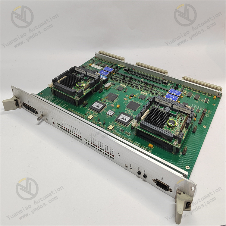
- Full Model Identifier: SDK-C0147 / 12004-101-00 / SBS04M17C
- Manufacturer: ALSTOM (integrated into the GE Vernova power control product line)
- Device Type: Backplane Bus Signal Interface Module for Industrial Control Systems
- Core Functions: System backplane bus networking, multi-board data relay transmission, bus signal conditioning & standardization, link impedance matching, communication timing scheduling, full-link hardware self-diagnosis, bus electrical isolation protection
- Compatible Systems: ALSTOM turbine control systems, GE Mark series DCS, power plant power excitation control systems, relay protection control systems, main control systems of combined cycle units
- Applicable Equipment: Gas turbines, steam turbines, combined cycle generator sets, CHP units, power excitation devices, power transmission & distribution protection equipment, integrated assemblies of system main control and IO boards
- Application Scenarios: Bus networking matching for new control systems, replacement of faulty legacy backplane modules, stability optimization of system buses, life extension renovation of power plant control systems, capacity expansion & upgrade of bus links
3.2 Electrical Performance Parameters
- Operating Power Supply: Standard industrial DC power supply complying with general cabinet power specifications of power plants, low power consumption, low heat generation and stable operation
- Operating Voltage: Compatible with standard industrial control voltage of power plants, adapting to conventional power distribution conditions of power control systems
- Transmission Performance: Stable bus transmission and precise timing, free of data packet loss, code error and delay drift, high consistency of parameters after long-term operation
- Impedance Characteristics: Adaptive bus impedance matching, dynamically adapting to load changes of multiple boards, suppressing bus signal reflection and waveform distortion
- Isolation Performance: Full-board electrical isolation design to effectively suppress surges, ESD, ground potential interference and bus electromagnetic crosstalk
- Electrical Protection: Built-in multi-layer protection mechanisms including overvoltage, overcurrent, short-circuit, surge, ESD and reverse voltage protection to withstand industrial electrical surges and power grid disturbance
3.3 Communication & Scheduling Parameters
- Communication Method: High-speed parallel backplane bus communication supporting concurrent data interaction of multiple modules, complying with original system networking specifications
- Communication Protocol: Compatible with ALSTOM/GE proprietary industrial control bus protocols for system configuration recognition, data relaying, timing synchronization and remote diagnosis
- Scheduling Mode: Intelligent timing priority scheduling with automatic communication bandwidth allocation to avoid data conflict and bus congestion
- Status Feedback: Real-time upload of bus operating status, link integrity, data transmission quality and bus fault alarm information
- Fault Tolerance Performance: Independent isolation of single-link faults without disrupting operation of the overall bus network to guarantee continuous system communication
3.4 Diagnosis & Protection Parameters
- Power-On Self-Test: Comprehensive inspection of full-board bus loops, transmission channels, impedance parameters, power supply modules and timing links
- Runtime Monitoring: Real-time detection of abnormal bus signals, link attenuation, data packet loss, bus congestion, intermittent communication and abnormal board temperature rise
- Fault Functions: Fault state locking, operation log storage, link traceability and remote system alarm upload for accurate localization of bus fault points
- Fault Tolerance: Independent isolation and locking of single-channel or single-link faults to block fault propagation and guarantee stable operation of the whole bus network
- EMC Rating: Complies with high-end industrial EMC anti-interference standards for power plants to withstand intensive electromagnetic radiation, equipment vibration and power grid fluctuation interference
3.5 Environmental Operating Parameters
- Operating Temperature: -20 ℃ ~ +70 ℃, suitable for wide temperature fluctuation in power plant control rooms
- Storage Temperature: -40 ℃ ~ +85 ℃
- Operating Humidity: 5% ~ 95% RH (non-condensing), adapted to constant temperature & humidity enclosed cabinet environments
- Protection Process: Military-grade three-proof conformal coating applied to PCB for dust, moisture, corrosion, oxidation and mold resistance, anti-aging
- Environmental Adaptability: Tolerates unit operational vibration, intensive electromagnetic radiation and alternating temperature & humidity fluctuation, supporting long-term energized continuous operation
- Operation Mode: 24-hour uninterrupted continuous operation to meet long-cycle unattended operation demands of generating units
3.6 Mechanical & Maintenance Parameters
- Mounting Method: Standard embedded rack slot installation compatible with dedicated backplane bus interfaces of the control system for stable connection, strong vibration resistance and reliable contact
- Structural Features: Highly integrated integrated backplane structure with compact size, no mechanical moving parts, stable bus transmission and ultra-low failure rate
- System Compatibility: Fully compatible with the complete bus architecture and configuration software of original ALSTOM and GE turbine main control systems, excitation control systems and power protection systems
- Replacement Characteristics: Standardized assembly design requiring no wiring modification, program revision, bus parameter calibration or timing commissioning after replacement, ready for commissioning upon power-on
- Maintenance Characteristics: No frequent routine calibration required; visualized and precise bus fault localization for convenient maintenance and low upkeep costs
4. Working Principle
After power-on, the ALSTOM SDK-C0147 backplane bus module automatically executes hardware initialization, bus parameter calibration, impedance matching self-test, timing link synchronization and power supply circuit inspection. It comprehensively verifies the integrity and operating status of the backplane bus network, completes communication handshake with all functional boards of the system after confirming no abnormalities, and enters normal bus networking operating mode.
During regular system operation, the module serves as the core hub for underlying bus networking and data interaction of the whole control system, undertaking core functions of multi-board data relaying, signal standardization, timing scheduling and link protection. All internal interactive data among main control modules, servo drive modules, IO acquisition modules and excitation control modules in the system are transmitted and relayed through the backplane bus of this module. Via built-in signal conditioning and impedance matching units, the module corrects signal attenuation, waveform distortion and timing offset generated during bus transmission in real time, and intelligently allocates communication priority and bandwidth resources for each board to avoid data conflict, bus congestion and timing disorder caused by concurrent communication of multiple devices. It guarantees accurate, synchronous and delay-free cross-module data transmission, providing stable underlying communication support for unit load regulation, servo closed-loop control, excitation parameter setting, equipment interlock protection and working condition linkage switching.
The module continuously monitors bus link status, signal transmission quality, load conditions and power supply status throughout operation. Once hidden hazards such as link abnormality, signal attenuation, data packet loss, bus short-circuit and intermittent communication are detected, it immediately triggers bus self-protection mechanisms to isolate faulty links and lock abnormal states. Fault codes and event logs are recorded synchronously and alarms are uploaded to the master control system to pinpoint faulty points. It effectively prevents fault propagation leading to whole-network communication abnormality, board offline, system logic disorder and unit working condition fluctuation, delivering all-round guarantee for stable underlying buses, reliable data transmission and accurate equipment linkage of turbine control systems, excitation control systems and power protection systems.
5.1 Bus Networking for Turbine Control Systems
As the core backplane bus unit of control systems for gas turbines, steam turbines and combined cycle units, it undertakes all internal data interaction and timing synchronization between main control boards, servo boards and IO boards, standardizing the underlying communication network of the system. It guarantees stable coordinated linkage of each module during unit startup/shutdown, load regulation, valve position servo control and dynamic correction under variable working conditions, serving as the fundamental core hardware for normal operation of turbine control systems.
5.2 Link Support for Generator Excitation Systems
Adapted to excitation control systems of power plant generator sets, it provides stable bus transmission channels for excitation main control modules, sampling modules and drive modules. It ensures real-time and accurate collection of excitation parameters, closed-loop operation and output of drive commands, stabilizes unit excitation regulation precision and grid-connected power quality, and avoids issues such as excitation fluctuation, reactive power oscillation and abnormal grid connection caused by unstable buses.
5.3 Communication Guarantee for Power Protection Systems
Applied to the construction of underlying buses for power plant relay protection and transmission & distribution control systems, it guarantees high-speed and stable transmission of fault signal collection, protection logical operation, trip command output and loop linkage protection. It eliminates protection refusal or misoperation caused by communication delay and data abnormality, forming a solid communication defense line for safe operation of power systems.
5.4 Bus Optimization & Renovation of Legacy Control Systems
For legacy ALSTOM/GE control systems suffering from bus aging, unstable signal transmission, data packet loss, intermittent board communication and disordered coordination of multiple boards, direct full replacement with this module realizes low-cost performance upgrade of underlying system buses with no cabinet, wiring or program modification required. It optimizes core performance of control systems, greatly improving communication stability and overall operational reliability of equipment and extending service life.
5.5 Bus Supporting for Industrial Automation Systems
Adapted to high-precision servo control and logical operation scenarios of large-scale energy industrial control and high-end industrial automation distributed control systems, it provides standardized bus networking solutions for scenarios with multi-module and multi-channel concurrent data interaction, solving the problem of unstable communication of industrial control systems under complex electromagnetic environments, and delivering core communication support for precise regulation, stable operation and intelligent linkage of automated systems.
![]()