Description
1. Product Overview
Full Model: DAPC100
Material Code: 3ASC25H209
Manufacturer: ABB
Product Name: Multi-channel Digital Input / Output Control Module / Industrial Real-time Data Acquisition & Logic Control Module
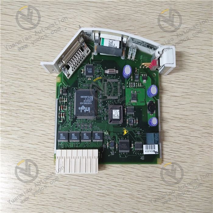
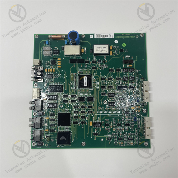
ABB DAPC100 (3ASC25H209) is a high-performance digital I/O logic control module designed for ABB Symphony and Industrial IT control systems. Developed for demanding industrial applications including power plants, chemical industry, metallurgy and water treatment, it serves as a core circuit board for field discrete signal acquisition, logic operation and equipment interlock control. The module integrates multiple digital input and digital output channels. It can continuously acquire discrete signals such as field switch status, equipment start/stop signals, interlock points and valve limit positions. Meanwhile, it executes switch control commands issued by the control system to drive field actuators for start/stop, interlock and protection actions. It is widely deployed in auxiliary unit control, process interlock, equipment sequence control and safety logic management.
Equipped with a highly reliable industrial main controller chip, the module delivers high-speed signal sampling and real-time logic operation. All channels feature independent electrical isolation with outstanding anti-interference capability, enabling stable operation under harsh industrial conditions with strong electromagnetic interference, drastic temperature variation, dust and humidity. It supports high-speed data exchange via the system bus to upload field point status accurately and execute upper-level control commands rapidly. Built-in hardware self-test, channel fault diagnosis and overload/short-circuit protection mechanisms ensure precise signal acquisition and reliable control output. Adopting a standard rack-mounted modular design, it supports non-destructive in-situ replacement and 24/7 continuous operation. As key hardware for discrete control loops of ABB DCS/PLC systems, only original identical replacement units are recommended to avoid interlock maloperation, signal loss and abnormal system logic caused by incompatible third-party modules.
2. Core Functions
Multi-channel discrete signal acquisition. Independent digital input interfaces collect real-time discrete data including equipment operating status, switch points, valve limit signals, relay status and interlock protection signals with accurate recognition and fast response without missing or false sampling.
Discrete logic control output. Digital output channels transmit switching commands to drive contactors, relays, solenoid valves, indicator lights and other field devices to implement manual/automatic equipment start-stop, process interlock switching, sequence control and fault interlock shutdown.
High-speed bus data communication. Natively compatible with the proprietary bus protocol of ABB industrial control systems. It establishes real-time communication with main controllers and host systems to upload channel status, fault information and point data, and receives control commands with low transmission latency and high stability.
Independent isolation protection for all channels. Each input and output channel is electrically isolated to eliminate crosstalk and signal coupling. A fault on one channel will not affect other channels or the whole module, significantly improving system fault tolerance and operational reliability.
Comprehensive self-diagnosis and fault alarming. Power-on hardware self-test and continuous runtime monitoring accurately detect open circuits, short circuits, overloads, abnormal signals, communication failures and hardware defects. On-board LEDs and pop-up alarms on the host system facilitate rapid fault location.
Industrial-grade interlock management. Supports local simple logic operation and coordination with complex host configuration logic to satisfy critical process requirements such as equipment interlock protection, sequential start-stop, fault blocking and safety linkage, ensuring safe and stable operation of production assets.
- Convenient maintenance without system shutdown. Supports online channel debugging, point configuration modification, status monitoring and fault reset. Daily maintenance, parameter calibration and troubleshooting can be carried out without halting the system, adapting to round-the-clock continuous production.
3. Technical Features
High-reliability real-time control performance. High-speed industrial main controller chip ensures fast signal sampling and command response as well as precise logic computation, meeting the demand for high-frequency, low-latency discrete control and preventing control delay and unintended triggering.
Integrated multi-channel design. Consolidated DI/DO channels with neat layout and high integration enable multi-point signal acquisition and control using a single module. This reduces the quantity of rack modules, saves cabinet space and suits high-density rack arrangement.
EMI-resistant architecture with electrical isolation. Full-channel opto-isolation effectively suppresses field interference, ground noise and voltage surges, avoiding signal drift, false triggering and communication anomalies under strong electromagnetic environments.
Multiple hardware safety protections. Built-in channel short-circuit protection, overload protection, overvoltage protection and reverse polarity protection prevent channel burnout and hardware breakdown caused by field wiring faults and abnormal loads, extending service life.
Stable long-term operation with low power consumption. Optimized low-power circuit design generates minimal heat. No parameter drift or channel failure occurs during long-term continuous operation; the unit achieves low failure rate and excellent stability for 24/7 service.
- Standardized and convenient replacement. Standard industrial rack slot form factor with native matching dimensions, pin definition and communication parameters for full-range ABB compatible control systems. Simple non-destructive in-situ replacement enables rapid commissioning without complicated configuration.
4. Specification Parameters
| Item | Parameter |
|---|---|
| Model | DAPC100 |
| Material Code | 3ASC25H209 |
| Product Series | ABB Industrial DCS/PLC Digital I/O Control Module Series |
| Product Type | Multi-channel Digital Input / Output Logic Control Module |
| Input Channel Configuration | 8 independent digital input channels |
| Output Channel Configuration | 16 independent digital output channels |
| Input Signal Type | Standard industrial discrete signal |
| Output Signal Type | Discrete level output, compatible with standard industrial actuators |
| Operating Power Supply | 24V DC industrial control power supply |
| Communication Mode | Proprietary system bus for high-speed real-time data exchange |
| Protection Mechanism | Channel short-circuit protection, overload protection, overvoltage protection, reverse voltage protection, open-circuit self-diagnosis |
| Isolation Type | Independent opto-isolation for all channels |
| Operating Temperature | -40℃~+70℃ (Continuous stable operation) |
| Storage Temperature | -45℃~+75℃ (Storage / Transportation) |
| Ambient Humidity | 5%~95%RH (Non-Condensing) |
| Protection Class | IP20 (Standard protection inside cabinet) |
| Mounting Method | Fixed installation in standard industrial rack slots; supports non-destructive in-situ replacement |
| Core Characteristics | Integrated multi-channel I/O, full-channel opto-isolation, fast signal response, multiple hardware protections, real-time self-diagnosis, strong anti-interference, long-term stable operation |
| Compatible Systems | ABB Symphony Plus, Industrial IT and full series DCS/PLC automation control systems |
| Typical Applications | Auxiliary equipment logic control in power plants, process equipment interlock protection, sequence control for chemical processes, discrete signal management for metallurgical equipment, water treatment automatic interlock systems |
5. Working Principle
After power-on, the module automatically executes full hardware self-test, channel initialization, bus communication handshake and loading of system configuration parameters. It sequentially verifies power supply voltage, channel circuits, isolation units and communication links. Once self-test passes, the module enters standby mode and waits for system commands and field input signals.
During normal operation, the 8 digital input channels continuously collect status signals from field switches, valves, relays and equipment. After opto-isolation, signal shaping and noise filtering, processed discrete status data is uploaded to the main controller to provide raw data for upper-level logic operation, status monitoring and fault judgment. Meanwhile, the module receives switching control commands issued by the host DCS/PLC. After command verification and logic judgment, corresponding control signals are transmitted via the 16 digital output channels to drive field actuators to perform equipment start-stop, interlock switching and fault blocking, realizing automatic logic control of field devices.
The module implements continuous full-channel real-time self-diagnosis to monitor DI/DO channel continuity, load conditions, circuit operation and bus communication quality. In case of channel short circuit, overload, open circuit, abnormal signal or communication interruption, the corresponding protection mechanism activates immediately to lock channel output and prevent fault propagation. Fault information is uploaded to the host system to support maintenance troubleshooting. After the fault is cleared, the module can recover automatically or via manual reset, guaranteeing safety, stability and accuracy of the whole interlock control system.
6. Common Faults and Troubleshooting
1. Module communication failure, unrecognized by host, all points offline
Causes: Abnormal, interrupted or under-rated 24V power supply; poor rack bus contact and loose communication wiring; lost configuration parameters or program error; bus address conflict with other devices.
Solutions: Stabilize power voltage and tighten power terminals; clean rack bus contacts, secure communication cables and troubleshoot bus links; reload module configuration and verify bus address to avoid conflicts; replace original module if communication hardware is damaged.
2. No feedback from input points; field signal exists but no display on system
Causes: Loose or broken input wiring; ageing and failure of channel opto-isolator; incorrect point configuration; channel locked after fault without reset.
Solutions: Inspect input wiring circuit by circuit, repair damaged cables and fasten terminals; check and correct point configuration; power cycle the module to release channel lock; replace module if input channel hardware is irreparable.
3. No output action; field equipment does not respond after command issuance
Causes: Open circuit or disconnected wiring on output loop; output channel locked by overload/short-circuit protection; ageing drive circuit; control command not properly transmitted from host.
Solutions: Inspect output loop and field loads to eliminate open circuit and load faults; remove abnormal loop conditions and power cycle to release protection lock; verify host control logic and command transmission; replace original module if output hardware fails.
4. Spontaneous point triggering, unsolicited actions and interlock disorder
Causes: Severe on-site electromagnetic interference and poor cabinet grounding; excessive induced voltage and signal crosstalk; channel parameter drift and abnormal sensitivity; incorrect configuration logic.
Solutions: Optimize cabinet grounding and shielding to suppress EMI; reorganize cable routing to avoid proximity to high-voltage cables and eliminate crosstalk; verify and revise system logic; replace module if hardware drift or defect occurs.
5. Single channel locked while other channels operate normally
Causes: Short circuit, leakage or overload on single channel wiring; fault or ground short of field load; channel ageing after long-term operation; micro-short circuit caused by dust and moisture on connectors.
Solutions: Isolate and inspect wiring and load of faulty channel to eliminate short-circuit and overload risks; clean dust and moisture on module terminals; restart to clear channel lock; replace module if fault recurs indicating hardware damage.
6. Abnormal points, communication failure and logic disorder after installing new module
Causes: New module not configured with matching bus address and parameters; mismatched terminal wiring definition; incompatible system firmware version; incomplete channel initialization calibration.
Solutions: Strictly verify wiring definition and correct misconnections; configure matching bus address and communication parameters, import standard system configuration; ensure compatible system firmware; complete channel initialization and power on for commissioning; put into service after successful testing of signal acquisition and control output.