Description
1. Overview
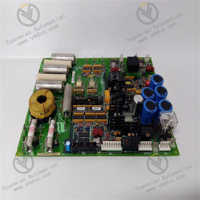
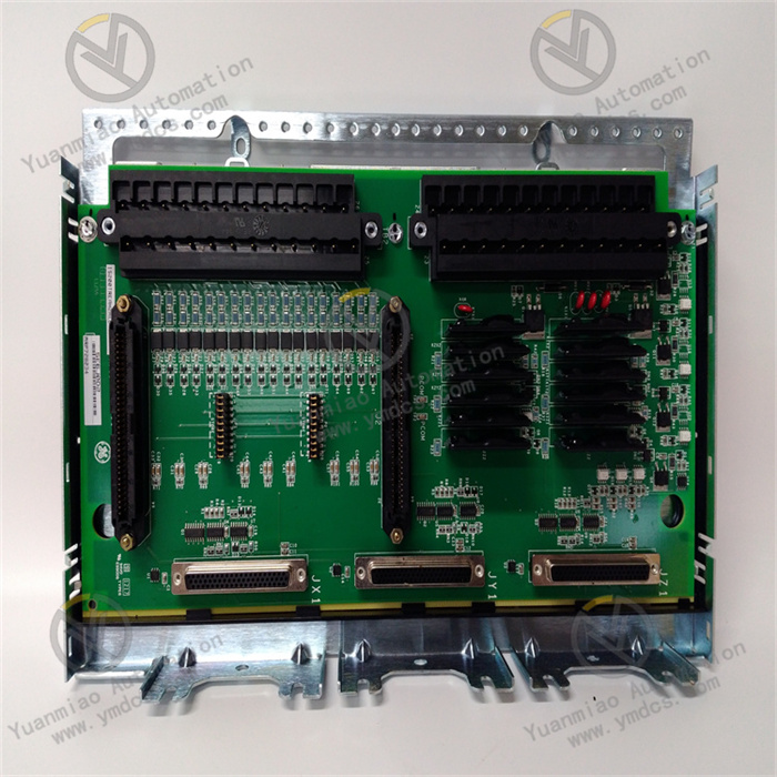
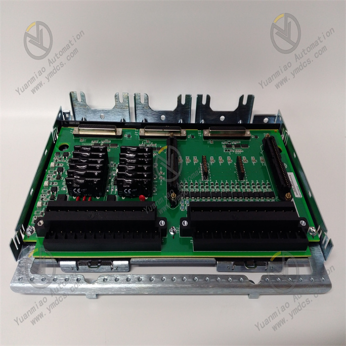
GE IS200BICIH1ACA is a dedicated Bridge Interface Controller (BIC) board for the GE Speedtronic Mark VI gas‑turbine control system. It is the core board for high‑power variable‑frequency drive and IGCT/IGBT bridge‑arm control of gas and steam turbines, widely used in thermal power, cogeneration and industrial gas‑turbine power‑control units. This board undertakes core functions including power‑bridge drive‑signal parsing, thyristor/IGCT switching‑logic control, bridge‑arm fault demultiplexing, drive‑link monitoring and system timing management. It serves as critical hardware for high‑power power conversion, stable bridge‑arm operation and drive safety protection of the unit.
The IS200BICIH1ACA adopts a highly‑integrated industrial‑grade circuit architecture, equipped with programmable logic devices, hardware watchdog and multi‑channel signal demodulation & protection units. It integrates signal isolation, timing calibration, fault discrimination and overload self‑locking functions, adapting to harsh operating conditions of high‑frequency switching and continuous heavy‑load operation of high‑power equipment in power plants. Natively compatible with GE Innovation‑series racks and Mark VI system backplane bus, it interfaces with various power‑drive daughter‑boards, comparison modules and voltage‑controlled oscillator modules for strong compatibility and expandability. As a key maintenance‑replacement spare part for power plants, it can directly replace aged and faulty boards of the same series without modifying system configuration or control logic. It rapidly restores unit power‑drive and bridge‑control functions and ensures long‑term safe and stable operation of gas‑turbine and steam‑turbine equipment.
2. Functions and Features
2.1 Core Functions
Power‑bridge Drive‑logic Control: Designed for IGCT and IGBT power switching devices. It outputs precise bridge‑arm trigger and turn‑off logic signals, manages timing of high‑power power conversion, ensures smooth start‑stop and orderly switching of the power bridge, and meets power‑regulation requirements for unit load variation and steady‑state operation.
Bridge‑arm Fault Demultiplexing and Discrimination: Receives multiplexed phase‑fault signals from the FOSB board set, performs fault demultiplexing, classification discrimination and accurate localization. It distinguishes various fault types such as bridge‑arm short‑circuit, drive abnormality, phase offset and device failure, and provides basis for accurate system alarming and protection actions.
Hardware Watchdog Real‑time Monitoring: Equipped with a 20 MHz system‑clock watchdog monitoring circuit to continuously track clock status of EPLD programmable logic devices. Upon clock anomaly, it immediately disables bridge‑arm trigger output, opens the main‑contactor circuit, cuts off drive power supply within 30 μs and prevents uncontrolled burnout of power devices.
Multi‑daughter‑board Coordinated Management: Natively supports auxiliary daughter‑boards including IS205AOCA analog comparison module and IS205DVAA dual voltage‑controlled oscillator module. It implements coordinated signal computation, parameter matching and logic linkage among multiple modules to build a complete closed‑loop power‑bridge control system.
System Bus Data Interaction: Complies with Mark VI backplane‑bus protocol. It bidirectionally transmits drive status, fault codes, operating parameters and system commands, synchronizes real‑time power‑bridge operating conditions, and supports unit load regulation, fault early‑warning and trip‑protection logic.
Comprehensive Hardware Safety Protection: Integrates multi‑level hardware‑protection mechanisms for over‑current, overload, timing anomaly, clock failure and drive‑link fault. It features fault self‑locking, fast power‑off and status‑locking functions to avoid secondary damage to power devices, drive units and the board itself.
Standardized Test‑point Monitoring: The board is equipped with 29 TP test points, enabling on‑site rapid inspection of circuit conditions, signal levels and clock status for convenient fault troubleshooting, board calibration and routine equipment inspection.
2.2 Product Features
High‑speed Safety Protection: Microsecond‑level fault‑response mechanism. It cuts off drive output instantly upon clock failure or bridge‑arm abnormality with fast response and high‑protection precision, effectively preventing runaway faults of high‑power power equipment and guaranteeing unit operational safety.
High‑density Modular Design: Incorporates more than 40 integrated‑circuit chips, multi‑channel signal‑processing units and replaceable fuses. Compact and highly integrated, it supports flexible expansion with various functional daughter‑boards to suit drive‑control scenarios of different power levels.
Power‑plant‑grade Anti‑interference Performance: Optimized for heavy‑EMI environments with high‑voltage apparatus, variable‑frequency units and high‑power switching equipment in power plants. Multi‑layer electrical isolation, signal shielding and filtering circuits eliminate false logic triggering and signal disorder caused by electromagnetic interference.
Full Mark‑VI‑system Compatibility: Fully compatible with GE Speedtronic Mark VI gas‑turbine control system and Innovation‑series racks. Backplane interfaces, bus protocols, control timing and hardware parameters fully meet OEM standards. Replacement requires zero adaptation work and no program modification.
Industrial‑grade Long‑term Reliability: Constructed with high‑temperature‑resistant, anti‑aging PCB substrate and military‑grade components. Protected by two replaceable 250 V / 200 mA fuses, it withstands cabinet high temperature, dust, humidity and minor vibration, and achieves very low failure rate under 24‑hour continuous heavy‑duty operation.
Convenient Maintenance and Fast Commissioning: Standard rack slot‑mounted design for easy installation and removal. Logic calibration and firmware pre‑loading are completed at factory. After replacing a faulty board, only simple condition verification is required for commissioning, greatly shortening unit outage duration.
3. Specifications
| Parameter Item | Technical Specification |
|---|---|
| Model | IS200BICIH1ACA |
| Device Type | Mark VI Bridge Interface Controller (BIC) Board |
| Compatible System | GE Speedtronic Mark VI gas‑ / steam‑turbine control system, Innovation‑series rack |
| Core Functions | Power‑bridge drive‑logic control, fault demultiplexing & discrimination, clock watchdog protection, multi‑daughter‑board coordinated management, bus data interaction, hardware safety self‑locking protection |
| System Clock | 20 MHz high‑precision reference clock |
| Fault Response Time | ≤ 30 μs (drive cut‑off response for clock fault) |
| On‑board Configuration | 2 backplane interfaces (P1/P2), 29 TP test points, 40+ IC chips, 2 replaceable 250 V / 200 mA fuses |
| Supported Devices | IGCT / IGBT power switching devices; functional daughter‑boards including IS205AOCA, IS205DVAA |
| Protection Mechanisms | Clock‑fault protection, bridge‑arm fault self‑locking, over‑current & overload protection, drive‑link‑fault protection, contactor interlock protection |
| Operating Temperature | 0 ℃ ~ +60 ℃ (standard power‑plant cabinet condition) |
| Storage Temperature | ‑40 ℃ ~ +85 ℃ |
| Ambient Humidity | 5%‑95% RH, non‑condensing |
| Ingress Protection | IP20 (cabinet‑internal installation) |
| Mounting Method | Slot‑mounted inside standard Innovation rack |
4. Working Principle
The GE IS200BICIH1ACA Bridge Interface Controller Board operates under a closed‑loop workflow: System‑command Reception → Daughter‑board Co‑computation → Bridge‑arm Drive Output → Real‑time Status Monitoring → Ultra‑fast Fault Protection. After power‑on, the board completes hardware self‑test, 20 MHz clock initialization, bus matching and daughter‑board parameter loading, and enters normal drive‑control state upon system synchronization.
Power‑regulation, bridge‑arm‑switching and load‑control commands issued by the Mark VI main controller are transmitted to this board via the backplane bus. Combined with computation results from AOCA comparison module and DVAA oscillator module, the board executes power‑bridge timing‑logic calculation and outputs precise IGCT/IGBT bridge‑arm trigger and turn‑off drive signals to govern high‑power power conversion and realize smooth unit‑load regulation. Meanwhile, it continuously receives multiplexed phase‑fault signals from the FOSB board set, and performs fault classification, localization and verification through demultiplexing algorithms to accurately identify bridge‑arm abnormalities.
During full‑time operation, the on‑board hardware watchdog monitors the 20 MHz reference clock and EPLD logic status, and collects key operating parameters including drive‑link status, contactor position and load current. Once hazards such as clock failure, bridge‑arm fault, over‑current/overload or communication anomaly are detected, ultra‑fast protection is triggered within 30 μs: bridge‑arm drive output is cut off, MA/MB main‑contactor circuit is opened, fault status is latched and fault codes are uploaded to the host system. This prevents catastrophic failures including power‑device breakdown and equipment short‑circuit burnout. After fault clearance, normal drive‑control can be restored via system reset, ensuring continuous, stable and safe operation of the unit power system.
5. Application Scenarios
Gas‑turbine Power‑control System: As core bridge‑control hardware for Mark VI gas‑turbine systems, it governs high‑power drive‑bridge‑arm operation, adapts to unit start‑stop, load ramping and steady‑state power‑generation conditions, and guarantees stable power conversion, accurate timing and reliable protection for gas turbines.
Steam‑turbine Variable‑frequency Drive Unit: Deployed in high‑power variable‑frequency drive systems of thermal‑power and cogeneration steam‑turbine units. It undertakes bridge‑arm logic control and fault monitoring, stabilizes unit power output and avoids load fluctuation and trip faults induced by drive anomalies.
Industrial High‑power Power‑conversion Equipment: Suitable for large‑scale power‑conversion devices in metallurgy, chemical and heating industries. It controls IGCT/IGBT power switching devices to realize high‑precision power regulation and equipment safety protection for heavy‑duty continuous‑production conditions.
Maintenance Replacement for Core Mark VI Boards: Directly replaces same‑model boards suffering from aging, logic disorder, frequent bridge‑control alarms or failed protection. No modification to system configuration, wiring or control program is required to quickly restore unit power‑drive capability.
Retrofit of Legacy Power‑plant Drive Systems: For legacy units troubled by chaotic bridge‑control logic, slow protection response and unstable power output, replacing with new BIC boards optimizes drive timing and fault‑protection performance, achieves low‑cost equipment upgrade and improves unit operational stability.
6. Common Faults and Troubleshooting
6.1 Unit reports bridge‑arm fault; power‑drive failure; contactor trip
Fault Causes: Abnormal board bridge‑control logic, faulty fault‑demultiplexing circuit, damaged drive‑output loop, mismatched daughter‑board (AOCA/DVAA), blown fuse.
Troubleshooting: Check system fault codes and inspect status of 250 V / 200 mA on‑board fuses; replace blown fuses. Inspect operating status of matched daughter‑boards and reseat daughter‑board connectors. Test drive‑output signals and timing via TP test points. If tripping and alarms persist after power‑device and external‑loop inspection confirms no field defects, the board hardware is damaged; replace IS200BICIH1ACA.
6.2 System clock‑fault alarm; drive interlock; unit cannot carry load
Fault Causes: Abnormal 20 MHz reference‑clock circuit, defective watchdog monitoring unit, EPLD programmable‑logic failure, clock‑signal loss.
Troubleshooting: Power‑cycle the board and system to reset clock logic. Clean board gold‑fingers and rack slots to eliminate poor‑contact issues. Inspect clock‑circuit performance and EPLD operating status. If clock alarms remain after ruling out system‑bus and power‑supply anomalies, core board circuitry has failed; replace the spare board.
6.3 Unstable unit load, power fluctuation, disordered bridge‑arm timing
Fault Causes: Degraded board timing calibration, abnormal daughter‑board co‑computation, attenuated signal filtering, false logic triggering due to electromagnetic interference, aged board components.
Troubleshooting: Improve cabinet grounding and shielding to mitigate strong‑EMI interference. Recalibrate power‑bridge timing parameters and refresh system configuration. Inspect daughter‑board connection and operation; tighten terminal connections. Enhance cabinet cooling to reduce board operating temperature. Replace the bridge‑control board if faults cannot be eliminated.
6.4 No board communication; system cannot recognize board; no response to drive commands
Fault Causes: Damaged P1/P2 backplane connectors, faulty bus‑communication circuit, abnormal board power supply, failed core computation chip.
Troubleshooting: Measure backplane supply voltages to rule out power‑supply fluctuation or loss. Clean and re‑seat P1/P2 backplane connectors to fix contact faults. Verify system‑bus configuration and restart bus services. Replace the board if communication still fails despite correct hardware connections and configuration.
6.5 Spurious protective trips, intermittent bridge‑control alarms, random tripping
Fault Causes: Aged board components, performance degradation under high cabinet temperature, circuit cold‑solder joints, drifted watchdog threshold, degraded anti‑interference capability.
Troubleshooting: Clear cabinet dust and air ducts, strengthen ventilation and heat dissipation to avoid board over‑temperature overload. Secure all connections between board, daughter‑boards and backplane. Inspect circuit solder joints for latent defects. Optimize on‑site electromagnetic environment. Replace with original‑equipment board if intermittent faults occur frequently.