Description
1. Overview
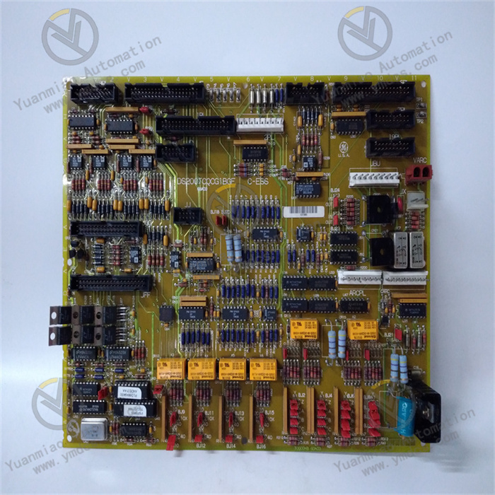
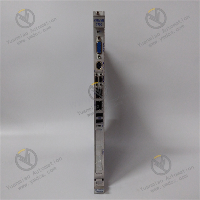
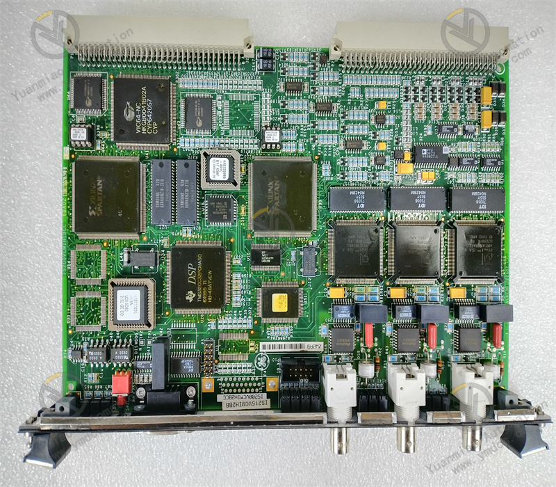
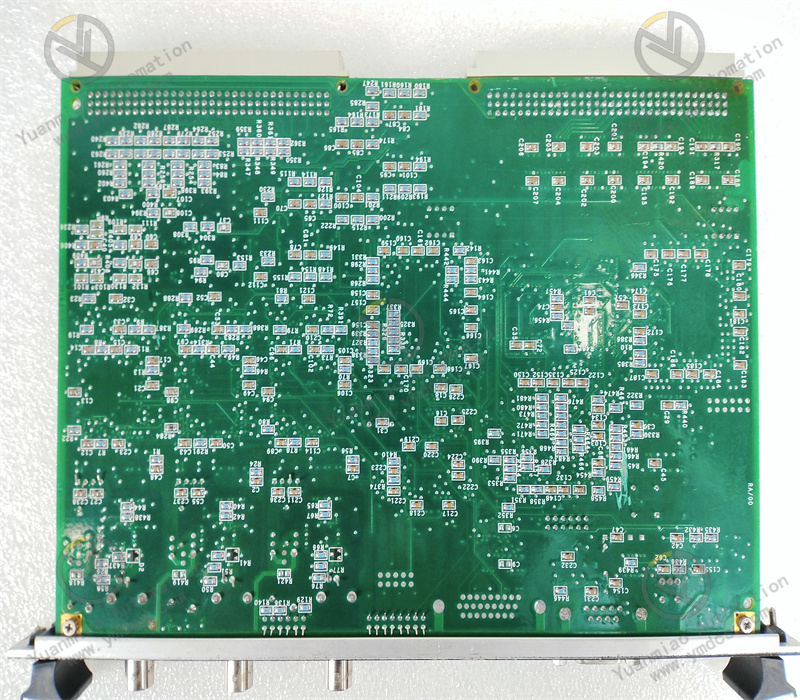
IS215VCMIH2C is a VME Bus Communication Master Board (VCMI) dedicated to GE Mark VI turbine control systems. It acts as the core communication hub within the rack for gas turbine and steam turbine control systems, and serves as the basic standard hardware model of IS215VCMIH2CA. As the system bus master controller, this board coordinates data interaction among all I/O boards, redundant control modules, extension racks and main processors in the rack. It is compatible with the TMR Triple Modular Redundancy fault-tolerant control architecture and designed for rigorous power plant operating conditions featuring 24-hour uninterrupted operation and strong electromagnetic interference. The board undertakes core tasks including system time synchronization, data voting, bus scheduling and network forwarding. It is an essential original hardware for stable operation, interlock protection and precise regulation of control systems for gas turbines, steam turbines and combined cycle units. No universal alternative models are available. It is widely adopted for maintenance replacement and system expansion of in-service GE Mark VI units.
2. Functions and Features
2.1 Core Functions
VME Bus Master Scheduling: Serving as the VME backplane bus master controller of the cabinet, it uniformly manages ID recognition, data transceiving, command distribution and resource scheduling of all I/O boards in the rack to realize coordinated operation of all rack-mounted hardware.
Redundant Data Voting and Fault Tolerance: Compatible with the Mark VI TMR triple redundant system architecture. It performs real-time comparison, fault judgment and data voting on three channels of homologous data, automatically eliminating abnormal data and preventing unit maloperation triggered by single-point hardware faults.
IONet Industrial Network Forwarding: Equipped with a dedicated system control network, it receives, parses and bidirectionally forwards IONet network data, establishing data transmission links between main control units, local I/O, remote extension racks and redundant protection modules.
High-precision Time Synchronization Management: Adopts hardware hard real-time time scheduling to accurately control system sampling cycles, regulation cycles and protection trip timing, meeting millisecond-level rapid protection and dynamic regulation accuracy requirements for gas turbines.
Full-range Hardware Self-diagnosis: Continuously monitors VME bus links, network communication status, board power supply and chip operating conditions. It triggers automatic fault alarms and status indicator prompts to support rapid fault localization and maintenance troubleshooting.
2.2 Product Features
High-reliability Fault-tolerant Operation: Natively supports the TMR triple modular redundancy fault-tolerant mechanism. A single board fault will not affect the operation of the entire system, fully complying with safety standards for critical power equipment.
High-speed Real-time Transmission Performance: Built on a 32-bit high-speed data transmission architecture with large throughput and ultra-low latency. It avoids data congestion and timing disorder, adapting to variable dynamic operating conditions of power units.
Adaptability to Harsh Industrial Environments: The entire board is coated with anti-corrosion PCB coating, delivering excellent dustproof, shockproof and anti-electromagnetic interference performance. It withstands complex power plant environments with high temperature, high humidity and strong interference.
Standardized Convenient Maintenance: Standard VME C-size double-slot form factor, supporting hot-swap online replacement. No shutdown or cabinet disassembly modification is required. No system configuration modification is needed after replacement, enabling rapid commissioning and greatly shortening equipment maintenance downtime.
3. Specifications
| Parameter Item | Technical Specification |
|---|---|
| Model | IS215VCMIH2C |
| Device Type | VME Bus Communication Master Board (VCMI) for Mark VI System |
| Bus Architecture | VME Industrial Backplane Bus, 32-bit High-speed Transmission |
| Communication Network | IONet System Control Network, RS-485 Serial Port |
| Operating Power Supply | DC 24V (Wide voltage tolerance: 18~32VDC) |
| On-board Regulated Output | DC 5V On-board Regulated Power Supply |
| Response Speed | 1ms high-speed hardware response, compatible with 25ms unit trip timing |
| Operating Temperature | -40℃ ~ +70℃ |
| Mechanical Specification | VME C-size, double-slot mounting, hot-swap support |
| Redundancy Mechanism | TMR triple modular redundant data voting, self-healing fault tolerance |
| Applicable Systems | GE Mark VI Gas Turbine / Steam Turbine / Combined Cycle Control Systems |
4. Working Principle
IS215VCMIH2C operates based on a closed-loop mechanism: Bus Initialization → Resource Enumeration → Data Interaction → Redundant Voting → Timing Control → Self-diagnosis & Maintenance. After power-on, the board first completes VME backplane bus initialization and self-test, automatically enumerates all I/O modules and control modules in the rack, assigns device IDs and completes registration of all hardware resources. During system operation, acting as the core bus hub, the board receives regulation and control commands issued by the main processor in real time, and accurately distributes commands to each front-end I/O board via the VME bus. Meanwhile, it synchronously collects field process measurement data, equipment status and loop feedback data, summarizes and processes the data before transmitting back to the main control unit for operation and regulation.
Under the TMR triple redundant architecture, the board conducts real-time comparison and voting on three channels of parallelly collected homologous data, automatically identifying and isolating abnormal erroneous data to guarantee uniqueness and accuracy of system control logic and monitoring data. The hardware timing unit continuously manages system sampling, regulation and protection action cycles to prevent timing offset and data delay. In addition, the board keeps monitoring bus links, network status and hardware conditions. It immediately triggers alarms and isolates abnormal links upon faults to ensure all-weather uninterrupted stable operation of the unit control system.
5. Application Scenarios
Heavy-duty Gas Turbine Control Systems: Serves as the core communication hub inside main control cabinets of GE Mark VI gas turbines. It supports the operation of core logic including combustion regulation, speed control, load adjustment and overspeed protection to stabilize gas turbine dynamic operating conditions.
Steam Turbine and Combined Cycle Power Plants: Handles bus data interaction and time synchronization for steam turbine governing systems, auxiliary machinery interlock systems and thermal control systems, meeting coordinated control requirements of combined cycle units.
Large Industrial Power Equipment Control: Deployed in fault-tolerant control systems of large compressors, industrial turbines and generator sets to realize multi-module coordinated communication and precise timing management.
Maintenance, Upgrade and Retrofit of Legacy Units: Fully compatible with all legacy GE Mark VI systems. Faulty boards of the same model can be directly replaced without modifying cabinet wiring, system configuration or control logic, enabling rapid equipment repair and system expansion.
6. Common Faults and Troubleshooting
6.1 Bus Communication Interruption, All I/O Modules in Rack Offline
Fault Causes: Abnormal DC24V power supply to the board; poor contact caused by oxidized backplane bus slots; crash of board bus program; failure of core main control circuit.Solutions: Inspect cabinet power supply voltage and fuses to eliminate power faults; power off, clean the board edge connectors and VME backplane slots then reinsert and secure the board; perform rack system restart and reset. If the fault persists, the board suffers hardware damage and shall be replaced with original IS215VCMIH2C.
6.2 Network Data Jitter, Intermittent Communication Disconnection and Frequent Parameter Fluctuation
Fault Causes: Degraded bus driving capability of the board; aging timing circuits; dust and oxidation on backplane interfaces; unstable links induced by on-site electromagnetic interference.Solutions: Verify standardization of cabinet grounding and shield grounding to eliminate electromagnetic interference; remove dust and oxidation from interfaces of the board and backplane; monitor bus communication quality continuously. Replace the board if jitter cannot be eliminated to restore communication stability.
6.3 Abnormal TMR Redundant Voting, System Alarms of Inconsistent Data
Fault Causes: Timing synchronization offset of the board; drift of sampling precision; failure of redundant link data interaction; mismatched firmware versions and parameters.Solutions: Verify consistency of firmware versions and configuration parameters among three redundant boards; recalibrate the system synchronous clock and reset redundant links. Directly replace the original board if hardware timing and voting functions fail.
6.4 RUN Indicator Off, FAIL Fault Indicator Steady On, Failed Power-on Self-test
Fault Causes: Damaged board firmware; abnormal main control chip/logic circuit; power-on self-test errors; core hardware failure.Solutions: Execute power-off restart and reset; re-flash matched original firmware. If self-test failures and alarms persist, the board is deemed defective and shall be replaced with an original board of the same model.
6.5 Delayed Data of Partial Measurement Points, Slow Equipment Regulation Response
Fault Causes: Degraded bus scheduling performance of the board; congestion caused by faulty downstream I/O modules; attenuation of hardware data processing rate.Solutions: Troubleshoot congestion points on downstream I/O boards and clear abnormal links; optimize system bus task scheduling logic. After confirming performance attenuation of the main communication board, replace the board to restore real-time system response capability。