Description
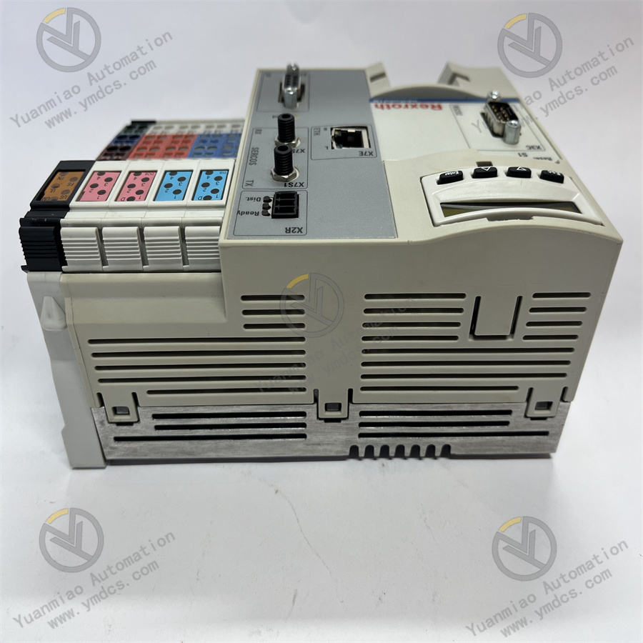
Functional Features High-performance Hardware Platform: Adopting advanced hardware design, it ensures stable and reliable operation in various industrial environments, providing a solid foundation for achieving high-precision control. Support for Multiple Programming Languages: It supports multiple programming languages such as ladder diagram, function block diagram, and sequential function chart. Users can select an appropriate language for logical programming according to their own programming habits and actual needs, making it convenient to implement various complex control logics. Rich Communication Interfaces: It is equipped with various communication interfaces such as Ethernet, Profibus, RS232, and Sercos. It can conveniently communicate with various devices such as the host computer, PLC, and sensors, realizing data transmission and sharing, and is easy to integrate into various automation systems. Good Expandability: Through the integrated PCI bus, additional modules can be connected to expand fieldbuses and technical interfaces, such as the DeviceNet and main axis encoder interfaces. It can also cooperate with Rexroth's Inline I/O system to easily achieve the expansion of the I/O unit. User-friendly Interface and Diagnostic Function: It is equipped with a display screen and operation buttons, which are convenient for users to perform on-site operation and monitoring. At the same time, it has a powerful diagnostic function, which can quickly and accurately locate system faults, reduce maintenance costs, and improve the maintainability of the system.
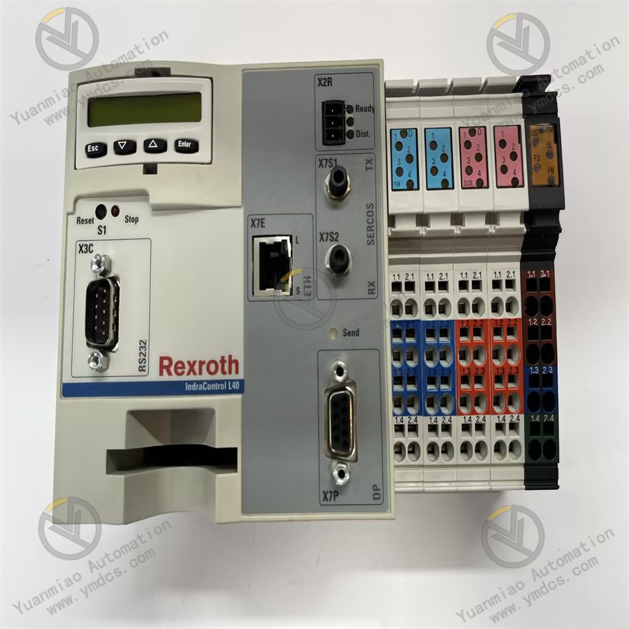
Technical Parameters Power Supply Voltage: The rated voltage is 24V DC, and the allowable voltage fluctuation range is -15% / +20% (when there is no residual ripple). Current Consumption: The maximum current consumption of Uls is 2.6A, and the maximum combined current consumption of Um and Us is 8A. Dimensions: Length 175.4mm, Height 120mm, Depth 75.9mm. Memory: The minimum DRAM is 64MB, and it is equipped with a Compact Flash memory card slot (the card and firmware need to be purchased separately) for storing application programs and runtime data. Input/Output: It has 8 high-speed digital inputs and 8 high-speed digital outputs. Operating Temperature: The ambient temperature during operation is 5°C - 55°C, and the storage and transportation temperature is -25°C - 70°C.
Application Scenarios Machine Tool Industry: Such as CNC machine tools, machining centers, etc., it can precisely control the movement of each axis of the machine tool, achieve high-precision machining operations, and improve machining quality and efficiency. Packaging Machinery: It is used in equipment such as packaging machines and filling machines to achieve precise conveying and positioning of packaging materials, as well as accurate movement control of the filling head, ensuring the accuracy and consistency of packaging. Printing Machinery: In equipment such as printing machines and die-cutting machines, it can control the rotation of the printing cylinder, the feeding of paper, and the position of the die-cutting tool to ensure high-quality printing and die-cutting processes. Robot Field: It is suitable for industrial robots and collaborative robots, providing precise drive control for the joint movement of robots, enabling them to complete various complex actions and tasks.
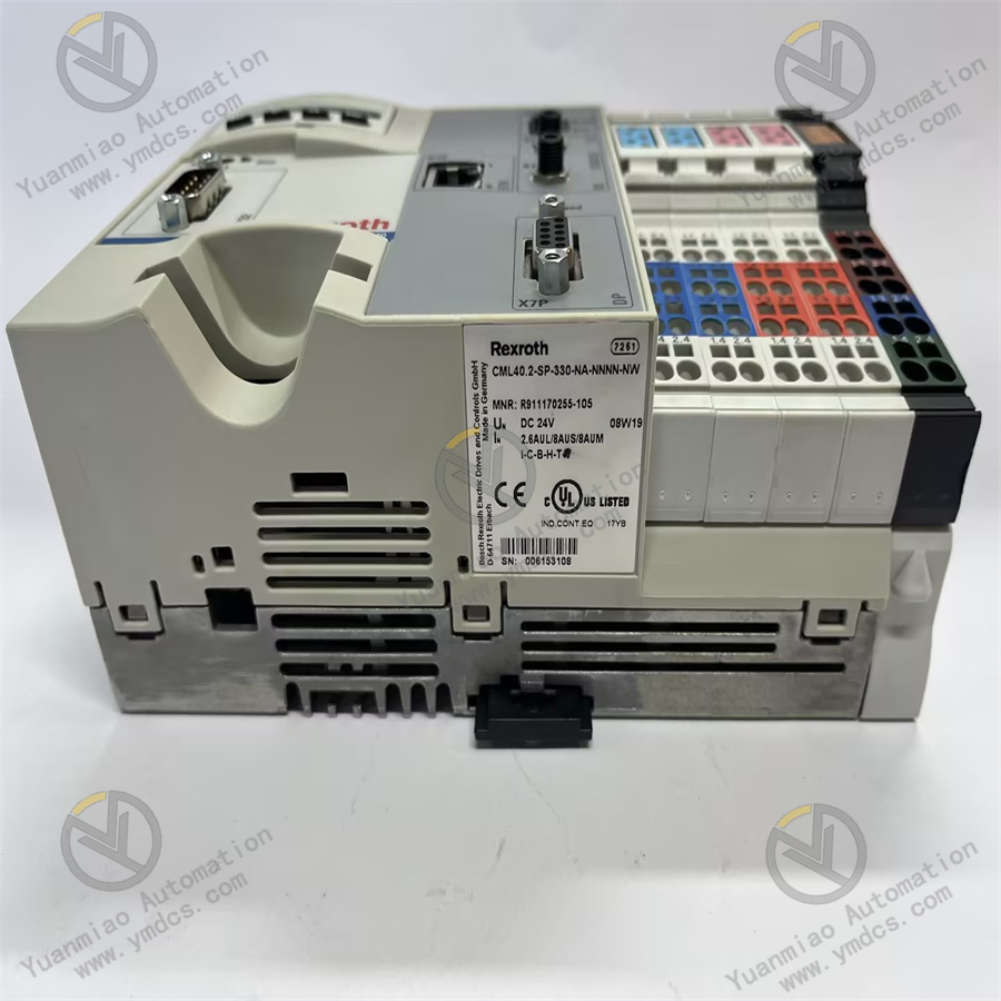
General Installation Steps and Related Precautions: 1. Installation Preparation Confirm the Model and Integrity: Check against the product label or instruction manual to confirm that the controller model is CML40.2 - SP - 330 - NA - NNNN - NW. Check whether there is any damage to the appearance of the product and whether the accessories are complete. Familiarize with the Installation Environment Requirements: The installation environment temperature should be maintained at -25°C - 70°C (during storage and transportation) and 5°C - 55°C (during operation). Avoid installing in a humid, dusty, or corrosive gas environment. Prepare Tools: Prepare the required installation tools, such as screwdrivers, wrenches, etc. 2. Selection of Installation Location Space Requirements: To ensure good heat dissipation of the controller and facilitate operation and maintenance, it needs to be installed in a location with sufficient space. At least 50mm of space should be left around for ventilation and wiring. Installation Method: The controller can be installed on a standard DIN rail inside the control cabinet or fixed on a flat mounting plate with screws. 3. Electrical Connection Power Supply Connection: The controller needs to be connected to a 24V DC power supply. The power supply should meet its current consumption requirements and must be a safely isolated power supply that complies with relevant standards (such as DIN EN 50178). Input/Output Connection: According to actual application requirements, correctly connect the input and output terminals of the controller to external devices (such as sensors, actuators, etc.). Pay attention to the firmness and correctness of the wiring to avoid short circuits or open circuits. Communication Connection: If communication with other devices is required, connect the corresponding communication cables according to the selected communication protocol (such as Ethernet, Profibus, RS232, etc.) and ensure that the communication parameter settings are correct.
4. Wiring Requirements
Cable Selection: Select power cables and signal cables of appropriate specifications according to the current magnitude and transmission distance to ensure that the voltage withstand level and insulation performance of the cables meet the requirements.
Wiring Method: Route the power cables and signal cables separately to avoid electromagnetic interference. If parallel wiring cannot be avoided, a certain distance (such as at least 100mm) should be maintained, or shielded cables should be used.
5. Grounding Connection
Grounding Requirements: To ensure the safe and stable operation of the system, the controller must be reliably grounded. The grounding resistance should be less than the specified value (such as 10Ω), and a thick enough copper wire (such as with a cross-sectional area of not less than 2.5mm²) should be used for the grounding cable.
Grounding Method: Connect the grounding terminal of the controller to the grounding busbar inside the control cabinet, and then ground the entire system through the grounding busbar.
6. Inspection after Installation
Appearance Inspection: Check whether the installation of the controller is firm, whether the cable connections are loose, and whether there is any damage to the appearance.
Electrical Inspection: Use tools such as a multimeter to check whether the power supply voltage is normal, whether the wiring of the input and output terminals is correct, and whether the communication lines are conductive.