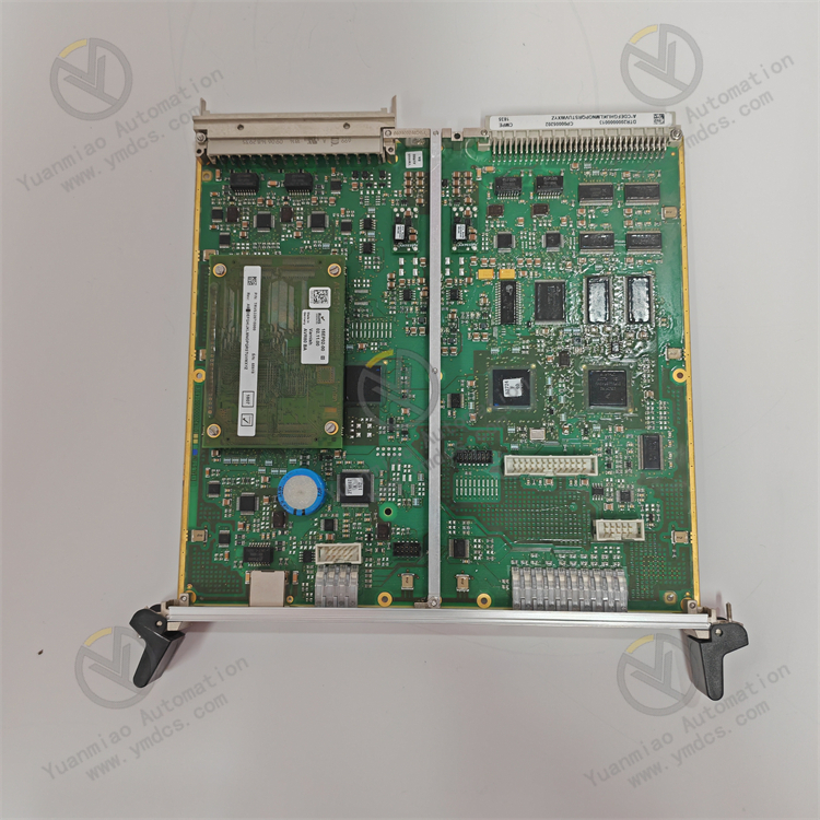
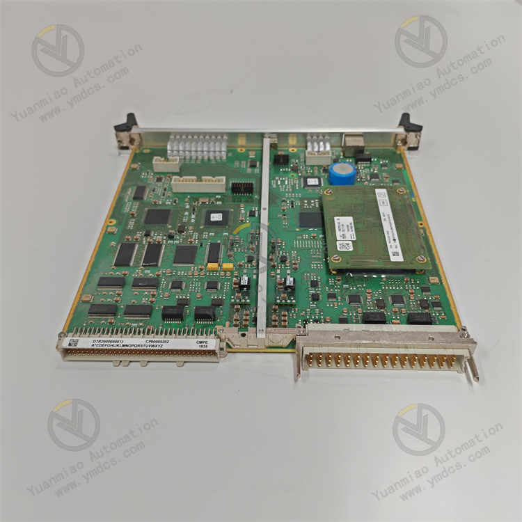
Description
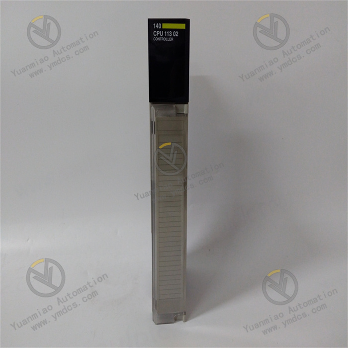
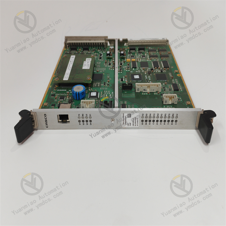
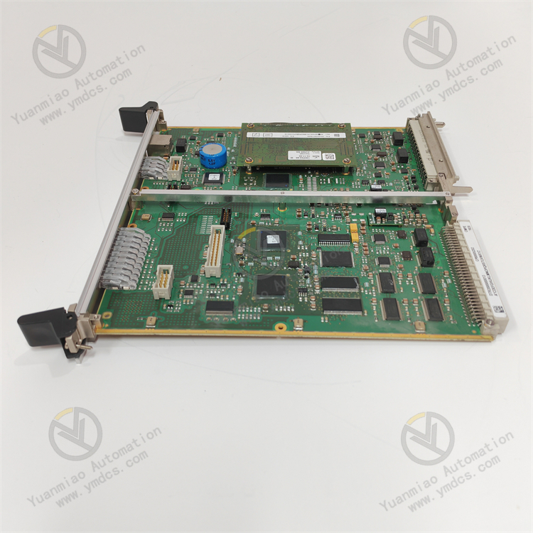
ALSTOM CMP1838 TRVCO62345000 CP00005202
Technical Parameters:
Power Supply Parameters- Rated Voltage: Commonly DC 24V, DC 48V, or AC 110V, AC 220V, etc., with allowable voltage fluctuations (e.g., ±10% or ±15%).
- Power Consumption: Generally ranges from several watts to tens of watts, depending on the module's functions and load conditions.
Input/Output Parameters
- Input Types: May include digital inputs (e.g., switch signals, discrete signals) and analog inputs (e.g., voltage, current signals).
- Number of Input Channels: Digital input channels may have configurations such as 8, 16, or 32 channels; analog input channels may have 4 or 8 channels.
- Input Signal Range:
- Digital input voltage range: DC 0–5V for low level (logic "0"), DC 15–30V for high level (logic "1").
- Analog input voltage range: 0–10V, -10–10V; current range: 4–20mA, etc.
- Output Types: Digital outputs (e.g., relay outputs, transistor outputs) and analog outputs (e.g., voltage, current outputs).
- Number of Output Channels: Similar to input channels, with multiple configurations available.
- Output Signal Range:
- Digital outputs can provide drive signals of different voltage levels (e.g., DC 24V, AC 220V).
- Analog output voltage range: 0–10V; current range: 4–20mA.
Communication Interface Parameters
- Communication Protocols: Such as CANopen, MVB, Profibus-DP, Ethernet/IP, Modbus, etc.
- Communication Rates:
- Common CANopen rates: 125Kbps, 250Kbps, 500Kbps.
- MVB rate: typically 1.5Mbps.
- Ethernet/IP rates: usually 10Mbps, 100Mbps, etc.
- Communication Address: Set the slave address via hardware DIP switches or software configuration to ensure uniqueness in the communication network.
Electrical Isolation Parameters
- Inter-Channel Isolation: Electrical isolation between input/output channels, with isolation voltages typically ranging from hundreds to thousands of volts (e.g., 500V, 1000V, 2500V).
- Input-Power Isolation: Isolation between the input circuit and power supply, with isolation voltages generally equivalent to or higher than inter-channel isolation.
- Input-Communication Isolation: Isolation between the input section and communication interface, with isolation voltages also in the range of hundreds to thousands of volts.
Mechanical and Environmental Parameters
- Mounting Methods: Commonly rail-mounted or screw-mounted.
- Dimensions: Length, width, and height vary by module complexity, typically ranging from tens to hundreds of millimeters.
- Operating Temperature Range: Generally -25°C to +70°C or wider.
- Humidity Range: Adaptable to 5%–95% relative humidity (non-condensing).
- Vibration and Shock Resistance: Meets relevant industry standards, capable of withstanding vibrations of specific frequencies and accelerations, as well as shocks of certain intensities.
Functional Features:
- High Reliability: Utilizes redundant design, fault-tolerant mechanisms, and high-quality electronic components to ensure long-term stable operation in harsh environments, reducing failure rates and guaranteeing continuous system operation to meet the extremely high reliability requirements of rail transit and other fields.
- Diverse Interface Types: Provides multiple standard interfaces (e.g., Ethernet, serial ports, CAN bus) to facilitate connections with train control systems, signaling systems, monitoring systems, and other external devices, enabling information sharing and collaborative operation.
- High-Precision Signal Acquisition and Processing: If equipped with analog input channels, it ensures high-precision signal acquisition, accurately capturing weak signals from various sensors and performing precise analog-to-digital conversion and digital signal processing to provide accurate data support for train control and protection.
- Strong Communication Capability: Supports multiple communication protocols (e.g., CANopen, MVB, Profibus-DP, Ethernet/IP), enabling seamless integration with train communication networks for fast and accurate data transmission and interaction. Features configurable communication rates and addresses to adapt to different network environments and system architectures.
- Flexible I/O Configuration: Digital input channels can receive various signal types (e.g., switch signals, discrete sensor signals) and offer multiple input channel configurations to meet input signal acquisition needs in different application scenarios. May include configurable input signal filter time constants to eliminate high-frequency interference pulses and improve signal stability.
- Excellent Electrical Isolation: Typically features good electrical isolation between channels, input and power supply, and input and communication, with isolation voltages ranging from hundreds to thousands of volts to prevent signal interference and electrical fault propagation, protecting the module and external devices from power fluctuations and interference and enhancing system stability and reliability.
- Harsh Environment Adaptability: Offers a wide operating temperature range (-25°C to +70°C or wider) to adapt to different environmental temperatures. Withstands humidity environments (5%–95% relative humidity, non-condensing) and has strong vibration and shock resistance, meeting relevant rail transit industry standards for stable operation in vibrating and impactful environments during train operation.
- Easy Installation and Maintenance: Adopts standardized mounting methods (e.g., rail mounting, screw mounting) for convenient fixing in control cabinets or equipment racks. The modular design facilitates disassembly and replacement, reducing maintenance costs and downtime. Equipped with self-diagnosis functions and fault alarm mechanisms to promptly detect internal faults and send alarm signals to the system, enabling rapid fault location and elimination.
General Operation Steps and Precautions (for reference):
Installation and Connection- Inspect the Module: Before installation, check the module’s appearance for damage, ensure all components are complete, and confirm the model matches requirements.
- Select Installation Location: Choose a suitable location based on equipment installation requirements, ensuring dry, well-ventilated conditions for easy operation and maintenance, while considering the module’s vibration and shock resistance requirements.
- Mount the Module: Securely install the module in the designated location using the specified method (e.g., rail mounting or screw mounting). For rail mounting, snap the module onto the rail and ensure a tight fit; for screw mounting, use appropriate screws to fix the module to the mounting plate.
- Connect Power Supply: Connect a suitable power supply according to the module’s power parameters (typically DC 24V). Ensure correct polarity to avoid damage from reverse connection. Firmly attach the power output cables to the module’s power terminals to prevent loose connections.
- Connect Input Signal Sources: Connect digital signal sources (e.g., switch signals, discrete sensor signals) to the module’s input terminals via appropriate cables. Ensure the signal source’s voltage range and type match the module’s input characteristics, and pay attention to cable shielding and grounding to reduce electromagnetic interference.
- Connect Communication Interfaces: If the module needs to communicate with other devices (e.g., PLC, TCMS), connect its communication interface to the target device’s interface via corresponding cables based on the communication protocol (e.g., CANopen, MVB, Profibus-DP, Ethernet/IP). Ensure cable length, shielding requirements, and electrical characteristics match for stable and reliable communication.
Parameter Configuration
- Set Communication Address: Use hardware DIP switches or software configuration tools to set the module’s slave address in the communication network, ensuring uniqueness for correct addressing and data interaction with the master station.
- Configure Input Parameters: Adjust input channel parameters (e.g., filter time constants) based on signal characteristics and application requirements. The filter time constant can be tuned to suppress high-frequency interference pulses and improve signal stability. If the module supports multiple input signal types (e.g., different voltage levels for logic "1" and "0"), configure them correctly.
- Configure Communication Parameters: Set communication rates and other parameters according to the protocol in use, ensuring consistency with other devices in the network to establish proper communication.
Operation and Monitoring
- Power On and Startup: After installation and configuration, power on the module for initialization and self-test. Observe the indicator lights to check startup status (e.g., the power indicator should light up to confirm normal power supply; if a communication indicator exists, it should light or flash after successful communication is established).
- Monitor Input Signals: Use the module’s monitoring software or the connected master device’s interface to observe input channel status and verify signal acquisition. Manually trigger changes in input signal sources (e.g., toggle switch signals) to check if the corresponding input channel status updates on the monitoring interface, verifying normal functionality.
- Monitor Communication Status: Monitor communication between the module and other devices for errors or abnormal data transmission. If issues arise, use the module’s error messages or diagnostic tools to troubleshoot, such as checking cable connections or communication parameter settings.
- Data Recording and Analysis: Record and analyze collected input data as needed, storing it locally or uploading it to a host system for further processing to understand equipment operation status, identify potential issues, or diagnose faults.
Maintenance and Servicing
- Regular Inspections: Periodically check the module’s operation (e.g., indicator status, communication integrity, input signal accuracy). Also, verify secure mounting and tight, undamaged cable connections, addressing any issues promptly.
- Module Cleaning: Regularly clean dust and dirt from the module’s surface to prevent heat dissipation issues. Use a clean, dry cloth; avoid wet or corrosive cleaners.
- Timely Replacement of Faulty Components: If a component fails (e.g., a damaged input channel or faulty communication chip), replace it promptly with a compatible original or certified alternative, following correct replacement procedures.
- Software Updates and Upgrades: Stay updated on the manufacturer’s software releases and promptly update the module’s firmware or related software to enhance performance, fix vulnerabilities, or add new features. Follow the manufacturer’s guidelines to avoid issues during the update process.