Description
GE MIFIIPI55E10HI00
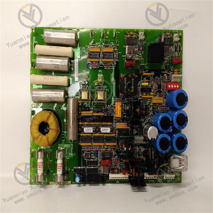
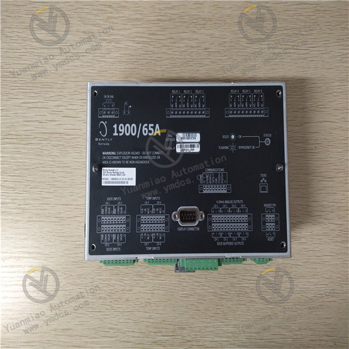
The GE MIFIIPI55E10HI00 is an intelligent input interface module. Serving as the "intelligent adaptation hub" connecting the system to diverse on-site signal sources, it mainly undertakes the tasks of collecting, isolating and converting, protocol adapting, and preprocessing different types of analog and digital signals in industrial sites. Its core function is to be compatible with various types of input signals such as thermocouples, RTDs (Resistance Temperature Detectors), 4-20mA current, and 0-10V voltage. Through the built-in signal conditioning and conversion circuit, it uniformly converts heterogeneous signals into standard digital signals recognizable by the system, which are then uploaded to the controller after protocol parsing. At the same time, it has the capabilities of signal calibration, fault self-diagnosis, and anti-interference optimization to ensure the accuracy and reliability of signal transmission in complex industrial environments. With the characteristics of multi-signal compatibility, high adaptability, and intelligent operation and maintenance, this module is widely used in scenarios such as chemical process control, metallurgical temperature monitoring, and energy and power parameter collection. It is a core interface component that ensures the control system realizes "unified access and accurate processing of multi-source signals".
1. Technical Parameters
1.1 Signal Access Parameters
1.2 Acquisition and Conversion Parameters
1.3 Interface and Communication Parameters
1.4 Environmental and Physical Parameters
2. Functional Features
2.1 Multi-channel and Multi-functional Compatibility, Simplifying System Architecture
Each of the 10 channels can be independently configured as thermocouple, RTD, current, voltage, or digital input, eliminating the need to configure dedicated modules separately according to signal types. For example, the same module can simultaneously collect the temperature (thermocouple), pressure (4-20mA), and valve switch status (DC 24V) signals of a chemical reaction kettle. The module cascading function can expand the input channels to 80, greatly reducing the number of modules in the control cabinet and lowering the complexity and cost of system integration.
2.2 High-precision Acquisition and Intelligent Calibration
The 16-bit AD conversion chip, combined with the optimized signal conditioning circuit, realizes high-precision acquisition of different types of signals. In particular, the thermocouple input integrates a cold-junction compensation circuit with a temperature compensation accuracy of ±0.1℃, which solves the error problem caused by cold-junction temperature drift in thermocouple measurement. It supports two calibration modes: offline calibration and online self-calibration. The parameters after offline calibration via dedicated equipment are permanently stored, and online self-calibration can be triggered through software to ensure the stability of acquisition accuracy during long-term use.
2.3 Multiple Anti-interference Design, Adapting to Complex On-site Environments
It adopts a triple anti-interference mechanism of "channel-level photoelectric isolation + module-level electromagnetic shielding + signal filtering". The isolation voltage between each channel and the power supply as well as other channels is ≥250V AC, which effectively isolates interference between different signals. The electromagnetic shielding shell can resist electromagnetic radiation generated by on-site frequency converters and high-power motors. The configurable digital filtering and analog filtering functions can accurately optimize signals with different interference intensities, balancing acquisition accuracy and response speed.
2.4 Full-dimensional Diagnosis and Convenient Operation and Maintenance
It has three-level fault diagnosis functions at the channel level, module level, and communication level, which can real-time monitor faults such as sensor disconnection, short circuit, signal over-range, module power abnormality, and communication interruption, with fault location accuracy reaching a single channel. Fault information is uploaded through LED indicators (each channel has a corresponding operation/fault light) and the communication bus. Combined with GE Proficy Machine Edition software, remote fault diagnosis can be realized. The hot-swapping function supports module replacement without shutting down the system, and combined with the automatic parameter synchronization function, it greatly shortens the operation and maintenance time.
3. Working Principle
3.1 Module Configuration and Signal Access
After the module is installed on the system rack, it establishes communication with the controller through Ethernet or RS-485 interface, and the controller automatically identifies the module model and firmware version. The channel configuration parameters, including the signal type, measurement range, sampling rate, and filtering parameters of each channel, are sent through GE Proficy Machine Edition software. The module completes the initialization of the internal circuit after receiving the parameters. On-site sensors or signal sources are connected to the corresponding channels through terminals, and different types of signals are correctly wired according to the terminal definitions.
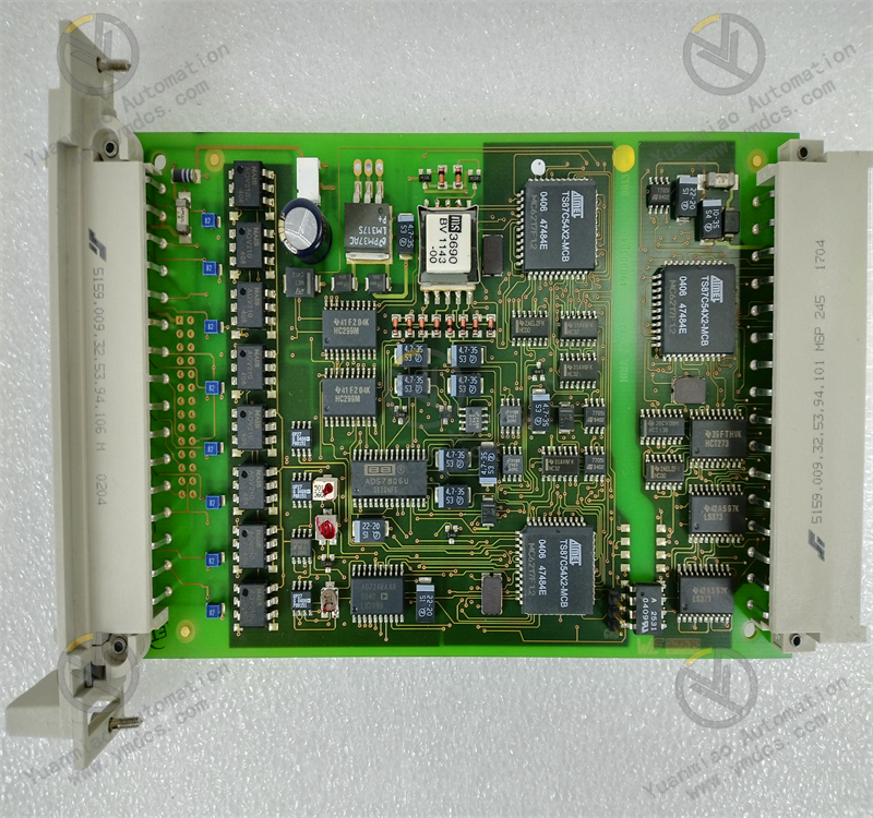
3.2 Signal Conditioning and Conversion
The accessed signals enter the corresponding processing units according to the configured types. Thermocouple signals are compensated by the cold-junction compensation circuit and then sent to the signal amplification unit; RTD signals are excited by a constant current source and then converted into voltage signals; current signals are converted into voltage signals through a sampling resistor; digital signals are sent to the filtering unit after photoelectric isolation. All analog signals are amplified and filtered, then sent to the 16-bit AD conversion chip to be converted into standard digital signals; digital signals are converted into logic signals after filtering.
3.3 Data Processing and Protocol Adaptation
The converted digital signals are sent to the core processing unit for preprocessing such as range conversion, unit conversion, and outlier elimination, and the data is standardized into a format that can be directly called by the controller. According to the configured communication protocol (such as Profinet), the processing unit encapsulates the collected data of 10 channels into communication frames and uploads them to the controller at the set cycle through Ethernet or RS-485 interface. Cascaded modules summarize data to the main module through the internal bus and then upload it uniformly to ensure data synchronization.
3.4 Status Monitoring and Fault Feedback
4. Common Faults and Solutions
4.1 Fault 1: Excessive Temperature Measurement Deviation of a Certain Thermocouple Input
Possible Causes
Solutions
4.2 Fault 2: No Data Collected or Fixed Data for a Certain Current Signal Input
Possible Causes
Solutions
4.3 Fault 3: Module Fails to Communicate with the Controller, and the Communication Indicator Flashes
Possible Causes
Solutions
4.4 Fault 4: Module Fails to Work Normally After Hot-swapping
Possible Causes
Solutions